info@kimaelectric.com
 +86 199 4451 2191




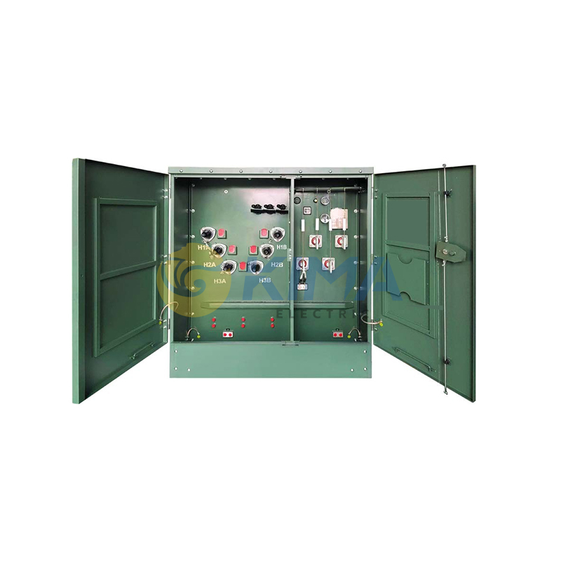
Oil-immersed three-phase pedestal Pad Mounted transformer
Product Overview
The three-phase pad-mounted transformer is ideally suited for large commercial buildings, industrial facilities, and utility networks that require higher power capacity and balanced load distribution. It is designed to step down medium-voltage power (up to 34.5kV) to lower usable voltages such as 208V/120V or 480V/277V.
Housed in a secure, tamper-resistant steel cabinet mounted on a concrete pad, it integrates fuses, switches, and connectors for safe outdoor urban power distribution. These transformers support efficient power distribution across multiple circuits, are designed to withstand outdoor environments, and can be customized according to different climate and grid standards.
The product is offered in Radial Feed and Loop Feed configurations to meet the requirements of different grid topologies.
Technical Specifications
|
Primary Voltage Rating |
2.4kV to 34.5kV |
|
Secondary Voltage Rating |
120/240V, 208V/120V, 480V/277V |
|
Capacity Range |
45kVA to 5000kVA |
|
Phases |
Three-phases (3ph) |
|
Rated Frequency |
50Hz or 60Hz |
Internal Components
Core Submersed Components
●Magnetic Core: Three-phase three-limb or five-limb structure, made of high-quality cold-rolled grain-oriented silicon steel laminations, providing a three-phase magnetic circuit.
●Windings: Wound with copper/aluminum foil or wire; HV side connected in Delta (D) or Wye (Y), LV side connected in Wye (y) with neutral lead-out (e.g., Dyn11).
●Submerged Three-Phase Load-Break Switch: Radial Feed type (2-position, responsible for transformer switching); Loop Feed type (4-position, controlling ring network switching of A/B incoming lines and on-load switching of this transformer).
●HV Dual-Fuse Protection System:
- ELSP Fuse: Fully fixed and submerged at the bottom of the oil tank, connected in series in the HV circuit, specifically intercepting high-current faults from severe internal short circuits of the transformer.
- Bay-O-Net Holder: The fuse element is fully submerged in the oil at the upper part of the tank, while the operating end is exposed in the front HV compartment.
●No-Load Tap Changer: Multi-position adjustment switch submerged in oil, for fine-tuning the turns ratio to adapt to grid voltage fluctuations.
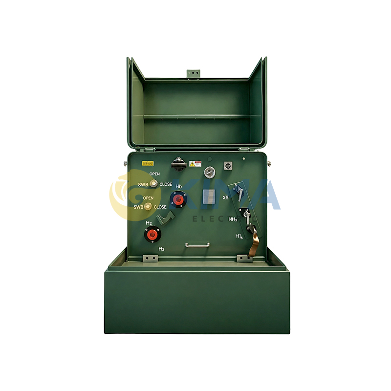
Front Left: HV Operating Compartment
After opening the pad-mounted transformer cabinet door, the left side is the HV room with no exposed live parts (adopting Dead Front design).
●HV Fully Insulated Bushing Wells/Inserts:3 for radial feed type, 6 (A/B two groups) for loop feed type, used for plugging in HV underground cables.
●HV Elbow Connectors: Key components for external cable connection, made of fully insulated rubber, safe to touch externally.
●Elbow-Type Zinc Oxide Arresters: Plugged into spare bushings, for protection against lightning overvoltage or switching overvoltage.
●Load-Break Switch Operating Rotary Handle: Mechanical knob extending to the front wall, operators can use a hot stick to toggle the 2-position or 4-position switch here.
●Tap Changer Control Handle:Manually rotated under power-off conditions to adjust voltage levels.
●Bay-O-Net Operating Ends:3 in total (1 per phase), with bright yellow locking hooks, allowing maintenance personnel to directly pull out and replace the submerged fuses with a hot stick.
Front Right: LV Operating & Distribution Compartment
●LV Insulated Bushings & Conductive Busbars:4 large copper busbars (A/B/C three phases + N neutral; if LV side is 0.4kV, the neutral point will be reliably grounded directly).
●LV Main Incoming Circuit Breaker: Molded Case Circuit Breaker (MCCB) for capacity ≤1250kVA; compact fixed Air Circuit Breaker (ACB) for capacity ≥1600kVA.
●Multi-Circuit Branch Breakers (Optional):2-6 small-current MCCBs can be equipped below the main switch for branch outgoing lines as per customer requirements.
●Integrated Protection & Measurement Components: Electronic phase-loss/unbalanced voltage protector (linked to the shunt trip of the LV main switch); Current Transformers (CT, monitoring phase currents); Multi-function power meter (real-time display of voltage, current, power factor, energy consumption, etc.); LV Surge Protective Device (SPD, protecting against LV side surge impacts).
Top & External Enclosure Auxiliary Components
●Pressure Relief Valve (PRV): Located at the top of the oil tank near the LV side, automatically relieving pressure when the tank is over-pressurized.
●Plate Radiators / Corrugated Tank Walls: Located on the left/right sides or directly at the rear of the oil tank, for circulating heat dissipation of transformer oil.
●Oil Thermometer & Oil Level Gauge: Standard visual pointer-type instruments for real-time temperature and oil level monitoring. integrable with the secondary control circuit for shunt trip protection during over-temperature or abnormal events.
●Oil Drain Valve: Located at the bottom of the enclosure, for drawing oil samples for testing during routine maintenance.
Insulating Oil
Premium mineral insulating oil complying with international standards.
Optional eco-friendly insulating liquids such as natural ester (vegetable oil) or silicone oil.
Structural and Design Features
- Tamper-Resistant & Secure: Features a fully enclosed, tamper-resistant design with lockable doors and concealed fasteners. This makes it highly suitable for ground-level installation in public areas, effectively preventing unauthorized access.
- Durable & Weather-Resistant Enclosure: Constructed from robust, corrosion-resistant steel, the enclosure effectively shields internal components from environmental factors such as dust and moisture, ensuring stable operation.
- Flexible Wiring Configurations: Offers both Live Front and Dead Front wiring options to accommodate diverse on-site installation and O&M requirements.
- Standardized Footprint: Manufactured according to standard base dimensions to ensure compatibility with existing infrastructure, facilitating easy equipment replacement or new installations and reducing construction complexity.
- Enclosure Structure: The enclosure is divided into front and rear sections
Front Section (HV & LV Operating Compartments): The HV compartment houses HV bushing wells (for mating with elbow connectors), the load-break switch operating handle, the no-load tap changer control handle, and the operating ends of the three Bay-O-Net fuses (one per phase).
The oil thermometer, oil level gauge, pressure relief valve, and drain valve are mounted on the rear tank wall, with their indicator dials and operating ports facing the front compartment for easy operation and maintenance.
The LV compartment contains LV bushings, high-current busbars, and LV distribution & integrated protection devices.
Rear Section (Oil-Filled Tank & Radiators), The transformer windings, core, HV load-break switch, and protective fuses are all housed inside the sealed oil tank for an integrated sealed design. The exterior of the tank is equipped with optimized plate radiators (or corrugated walls) to achieve efficient ONAN (Oil Natural Air Natural) self-cooling.
- Protection Features: The HV side adopts a dual-fuse (Bay-O-Net fuse + ELSP current-limiting backup fuse) full-range protection scheme, which significantly reduces overall equipment cost while providing excellent fault isolation capability. The LV side is equipped with an electronic phase-loss protector, which can instantly trigger the shunt trip of the main incoming breaker when the system experiences phase loss or severe voltage imbalance caused by HV single-phase fuse blowout or external abnormalities, ensuring the safety of three-phase loads. The HV side is configured with a submersed oil load-break switch, laying the foundation for ring network automation.
Typical Applications
Residential Developments: Powers entire residential districts and townhouse communities.
Commercial Centers: Supplies power to shopping malls, hospitals, and office buildings.
Renewable Energy: Serves as a step-up or step-down transformer for solar power plants and wind power installations.
Industrial Facilities: Provides stable power to manufacturing plants and large warehouses.
Frequently Asked Questions (FAQ)
Q: What maintenance is required for pad-mounted transformers?
These transformers require minimal maintenance, primarily consisting of periodic inspections for oil leaks, corrosion, and ensuring the enclosure remains secure and free of debris. Regular testing of built-in switches and protective fuses is recommended to ensure proper operation in the event of a fault or overload.
Q: What information is needed to obtain a quotation?
To receive a prompt and accurate quotation, please provide the following core parameters:
Basic Transformer & Capacity Parameters
- Rated Capacity (kVA)
- Primary and Secondary Voltage Levels
- Rated Frequency (50Hz or 60Hz)
- Number of Phases (Single-Phase or Three-Phase)
- Winding Material: Both copper and aluminum windings are supported, each with distinct advantages in cost and performance.
- Vector Group Symbol
- Other Requirements (such as applicable standards, or special protection ratings, instrument accessories, etc.)
Enclosure & Environmental Adaptability
Enclosure Material:
- Standard Steel Plate (coated with high anti-corrosion paint).
- Stainless Steel (304 or 316L, designed for coastal areas with high salt mist, high humidity, or severe pollution).
- IP Rating & Color:g., IP43 or IP54; specify if there are special requirements for the exterior color (e.g., Green, Harbor Grey) to blend with public landscape aesthetics.
Special Requirements
- Installation Altitude & Temperature: If installed at altitudes exceeding 1,000 meters, or in environments where the temperature is consistently above 40°C or below -25°C, this must be declared in advance. The manufacturer will need to apply altitude corrections for external insulation or select special low-temperature sealing components.
- Cable Entry/Exit Direction: The standard for pad-mounted transformers is bottom entry and bottom exit (cables accessed from the bottom via concrete foundation trenches). Special requirements (e.g., side entry) must be specified.
Primary Wiring & Grid Topology
- System Topology Type:
Radial Feed: Equipped with a 2-position load break switch and 1 set of high-voltage bushings.
Loop Feed: Equipped with a 4-position load break switch (specify whether V-grip or T-grip blades are required) and 2 sets of high-voltage bushings.
- High-Voltage Wiring Configuration (Front Structure):
Dead Front: Fully insulated front wall (requires mating elbow cable connectors); typically specify whether it is 200A separable (plug-in) or 600A fixed type.
Live Front: Traditional exposed porcelain bushing wiring.
Protection & Control Component Requirements
- High-Voltage Side Fuse Configuration: Does it adopt the standard "Dual-Fuse Full-Range Protection" (i.e., Bay-O-Net insert fuse + ELSP current-limiting backup fuse)? Is it necessary to specify the fuse brand or specific current-breaking capacity?
- Low-Voltage Side Distribution Requirements: Is an electronic phase-loss protector mandatory? Specify the rated current, breaking capacity (kA), and number of circuits (e.g., need for multi-circuit outgoing lines) for Air Circuit Breakers (ACB) or Molded Case Circuit Breakers (MCCB).
- Cooling & Temperature Control System: Pure natural cooling (ONAN) or forced air cooling with fans (ONAF, for temporary overload capacity expansion)?
If you are looking for reliable power support for your project, please contact the Kima Electric team.
- Direct Factory & Manufacturer: We are a professional China Oil-immersed three-phase pedestal pad-mounted transformer manufacturer (available in 11kV,13.2 kV,13.8 kV,33kV,34.5kV and other voltages). Our factory is equipped with advanced production facilities and accepts OEM/ODM orders.
- Reliable Supplier: We serve as a trusted international supplier for global buyers looking to source high-efficiency and low-loss oil-immersed three-phase pedestal pad-mounted transformers from China.
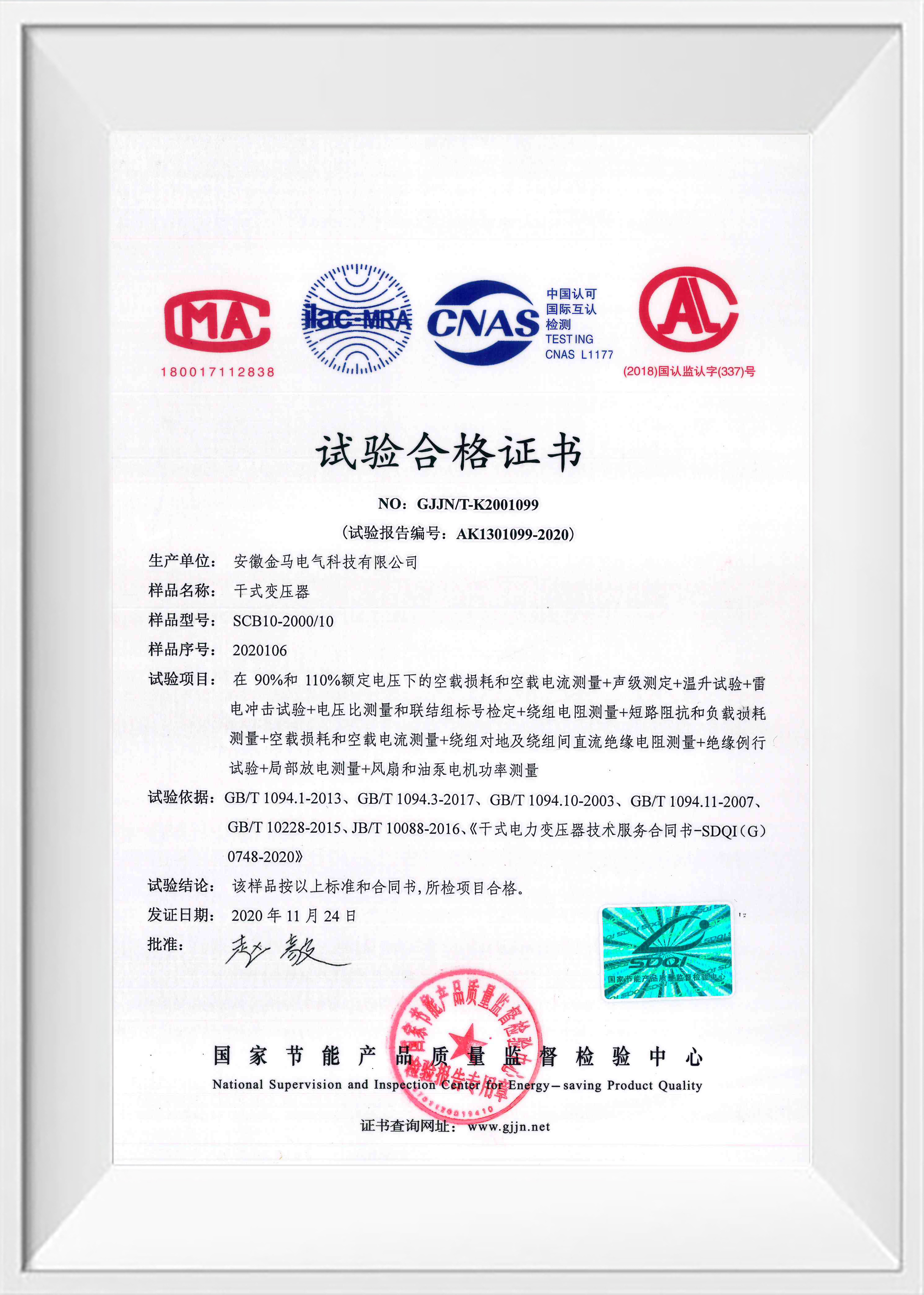
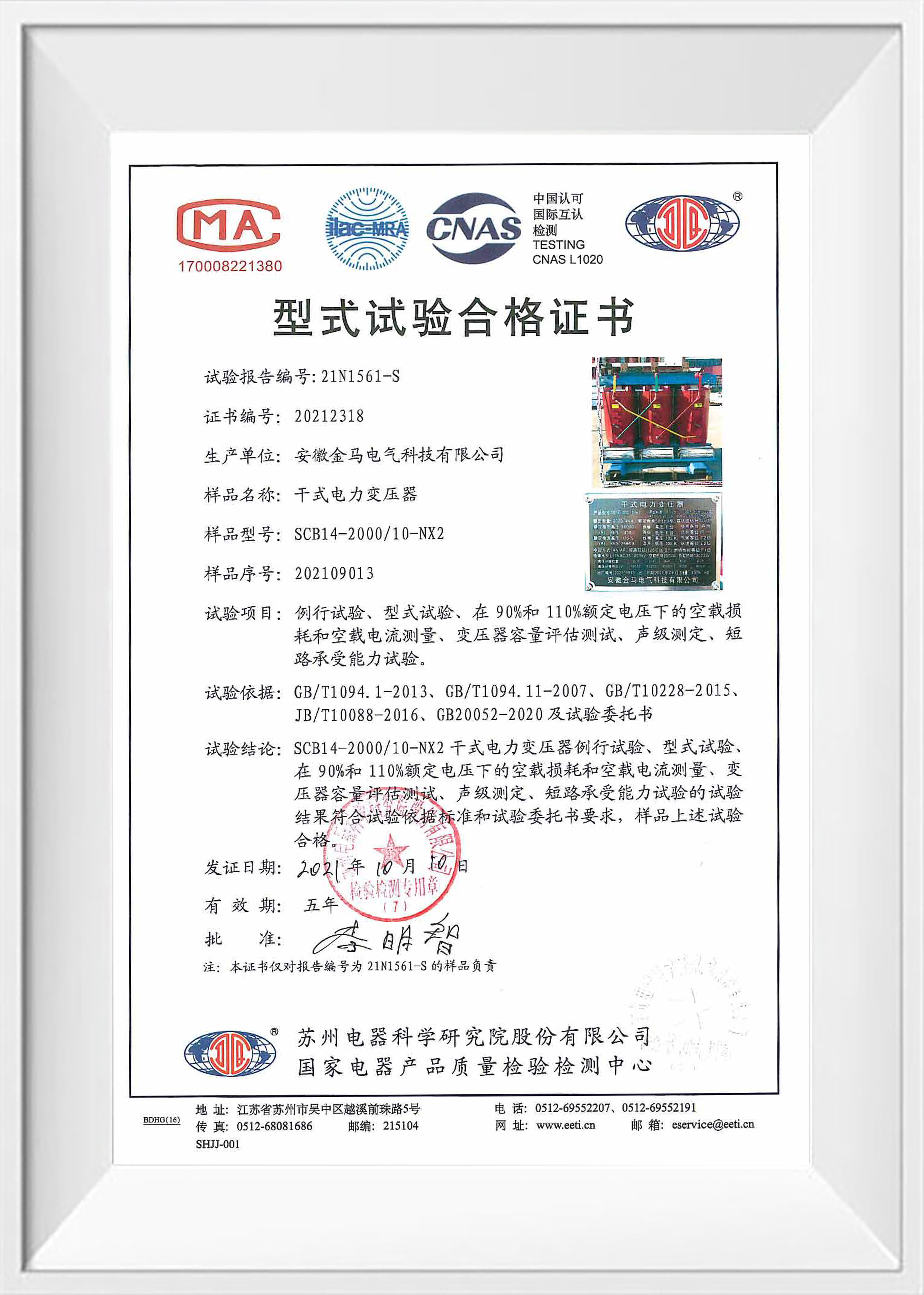
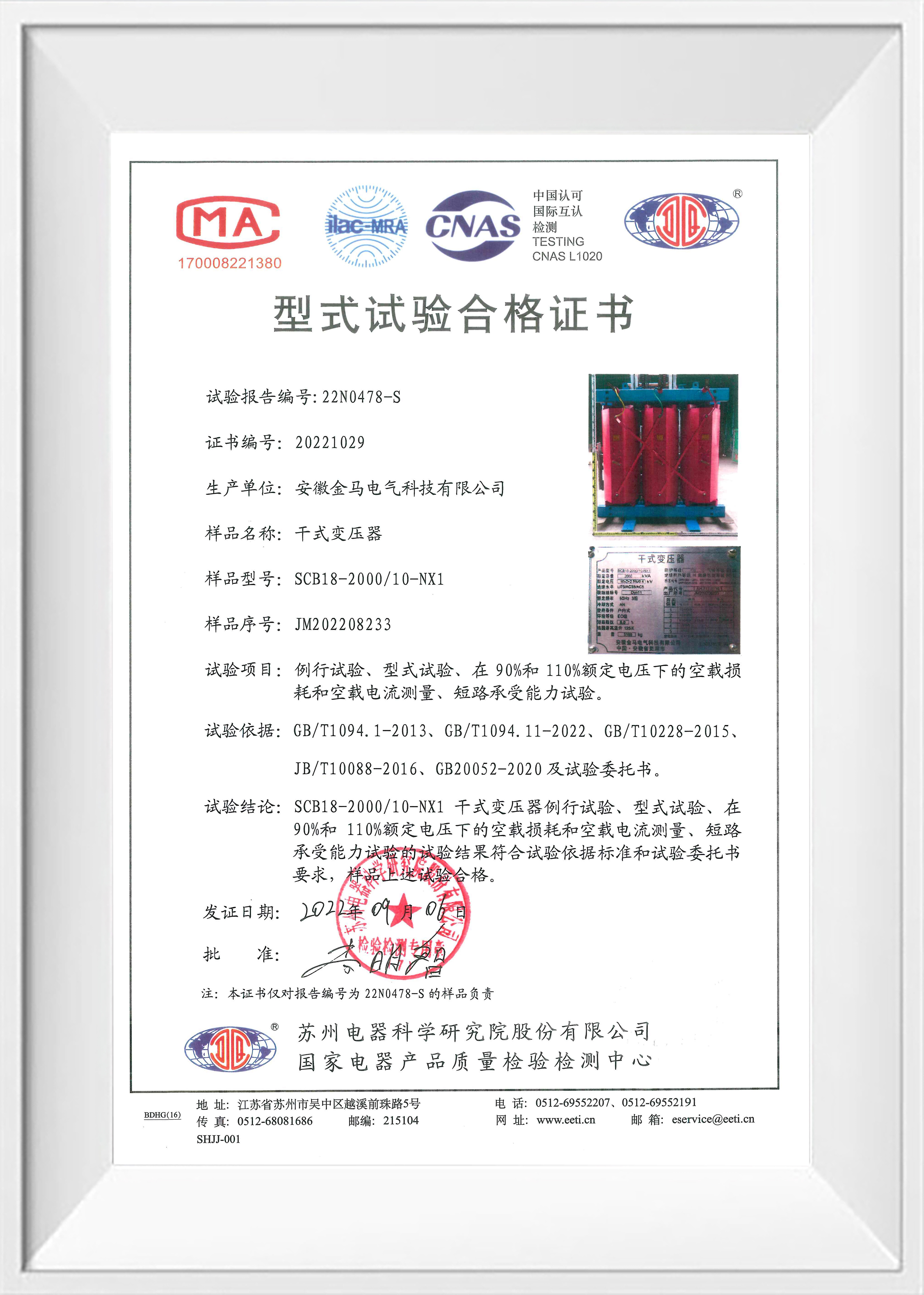
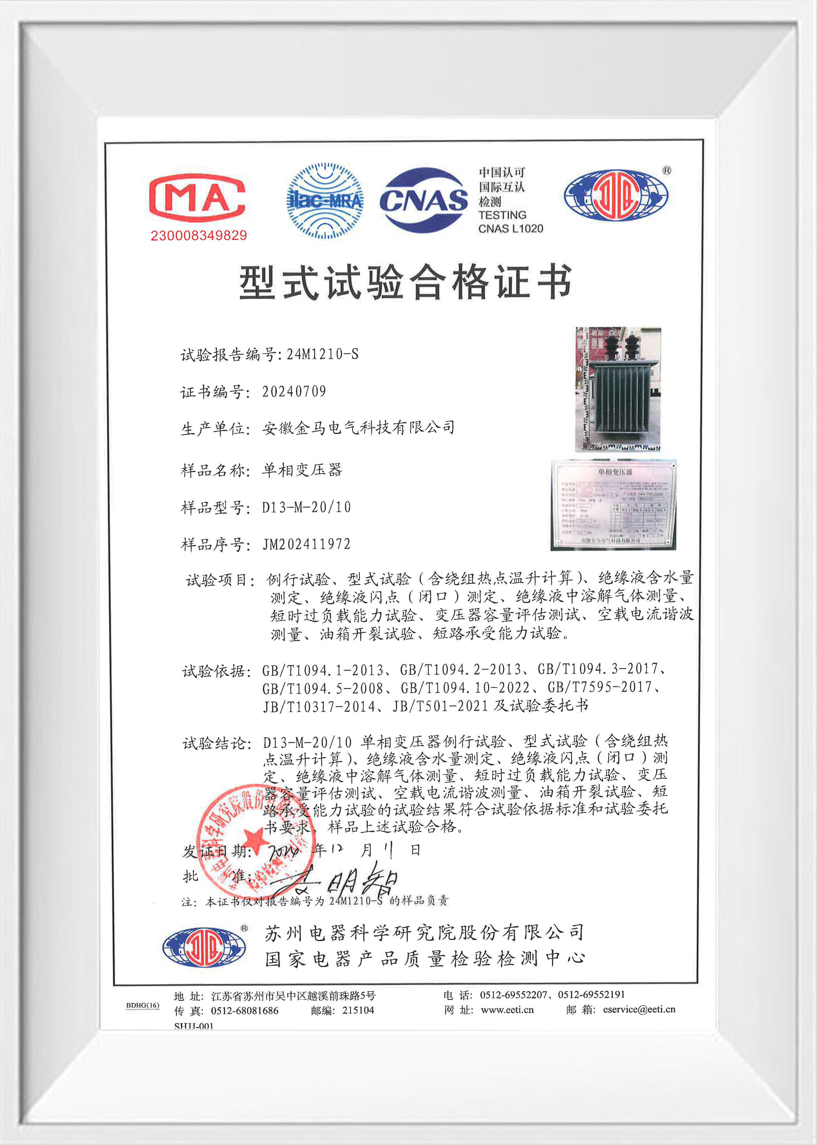
- International Standards & Global Reach: Our transformers are rigorously tested to comply with IEC 60076 and other international standards. We export to diverse markets across Southeast Asia, Africa, and the Middle East, adapting to various local grid environments.
- Competitive Quotation: Contact us today to discuss your project requirements, get a customized solution, and receive a free wholesale quote.
◆ Convenient Inquiry Process
You may contact us through various channels, including our website and email. You can also download and fill out the "Inquiry Request Form" from our official website, or directly provide your existing technical documents and drawings as the basis for requirement assessment. We will provide a quotation as soon as possible.
◆ Production & Quality Control
●Prior to formal production, we will provide detailed technical proposals including specifications and structural drawings for your review and confirmation.
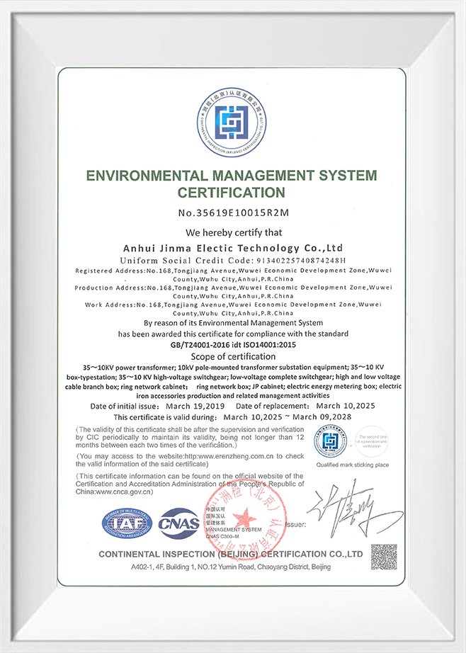
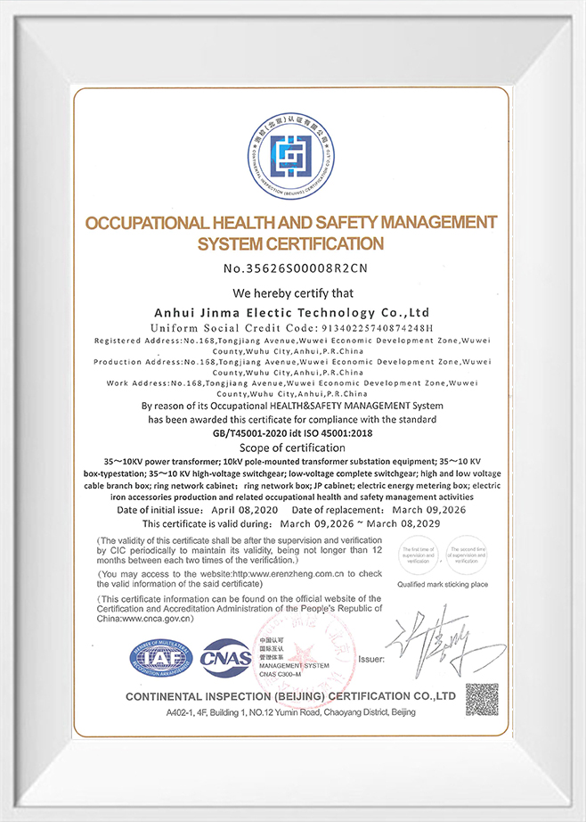
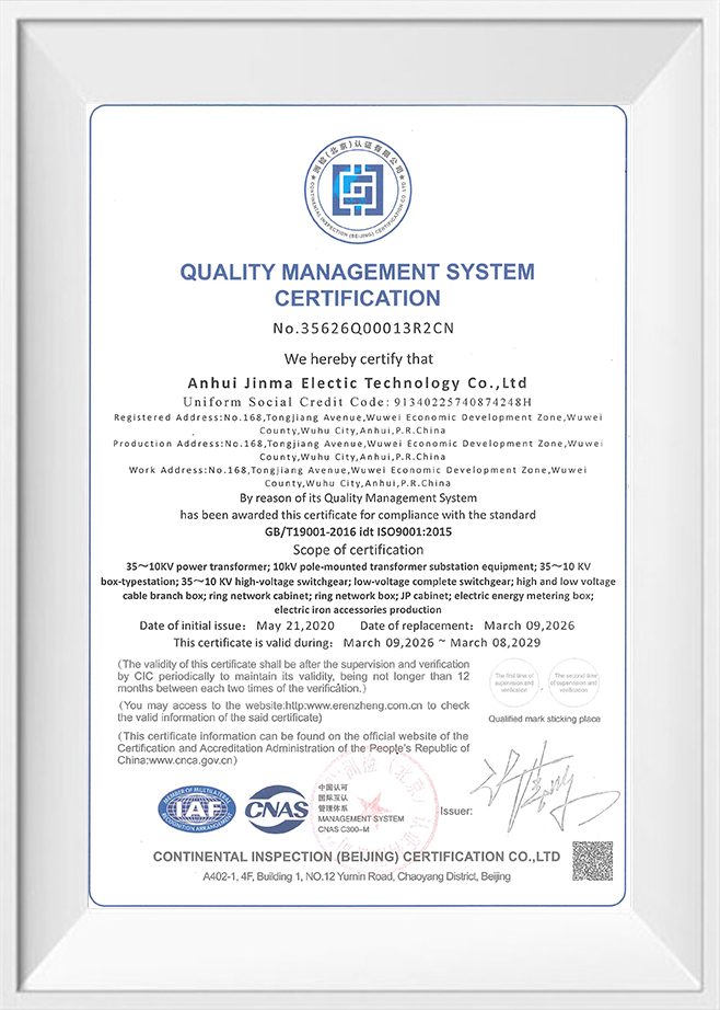
●We strictly implement the ISO quality management system, with comprehensive monitoring of raw materials, production processes, and finished product inspections to ensure stable and reliable quality for every customized product.
◆ Delivery & After-Sales Service
●Packed in specialized wooden crates compliant with international standards, lined with high-performance moisture-proof materials to ensure absolute safety and dryness during long-distance transportation.
●Detailed user manuals, maintenance manuals, and related documentation are provided with each shipment.
●Remote or on-site installation guidance and commissioning services are available upon request.
●Comprehensive after-sales support including technical consultation, troubleshooting, and spare parts supply to ensure long-term stable operation.
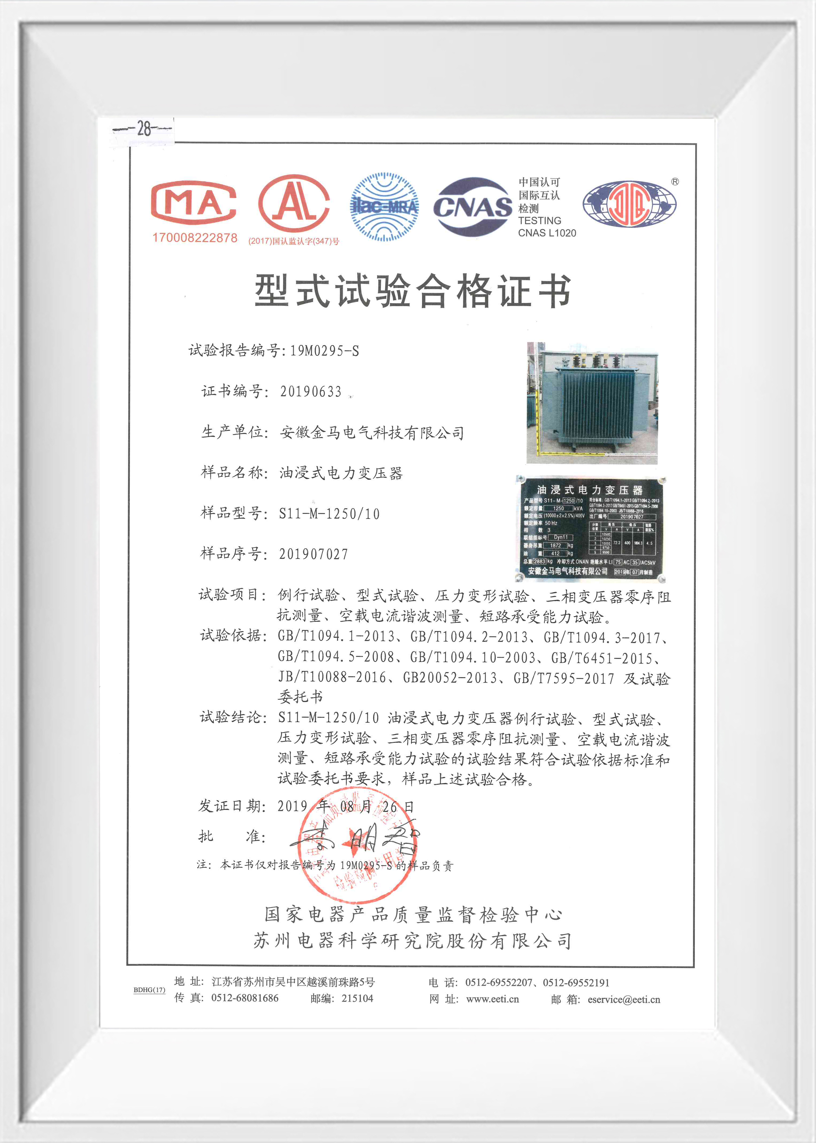
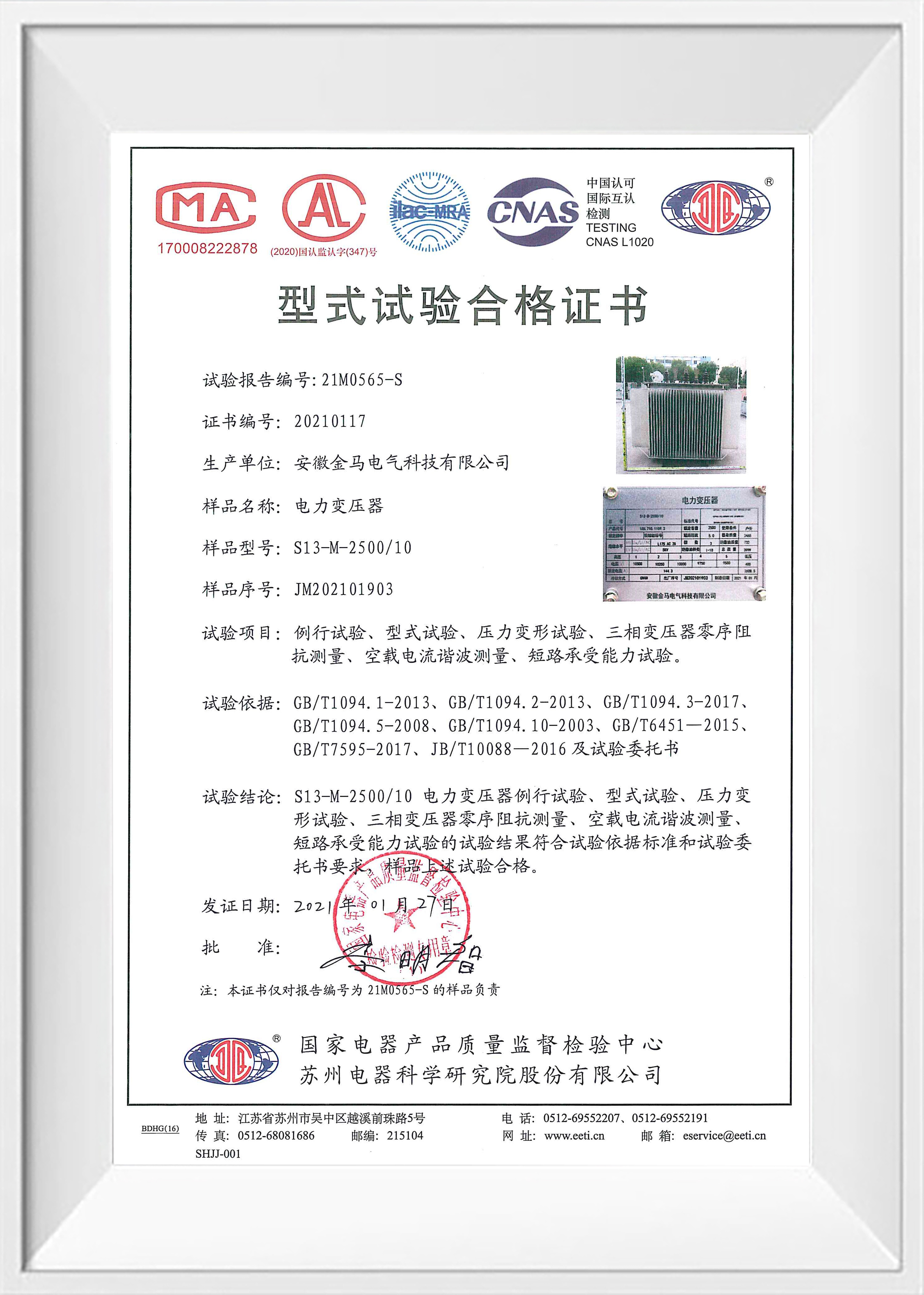
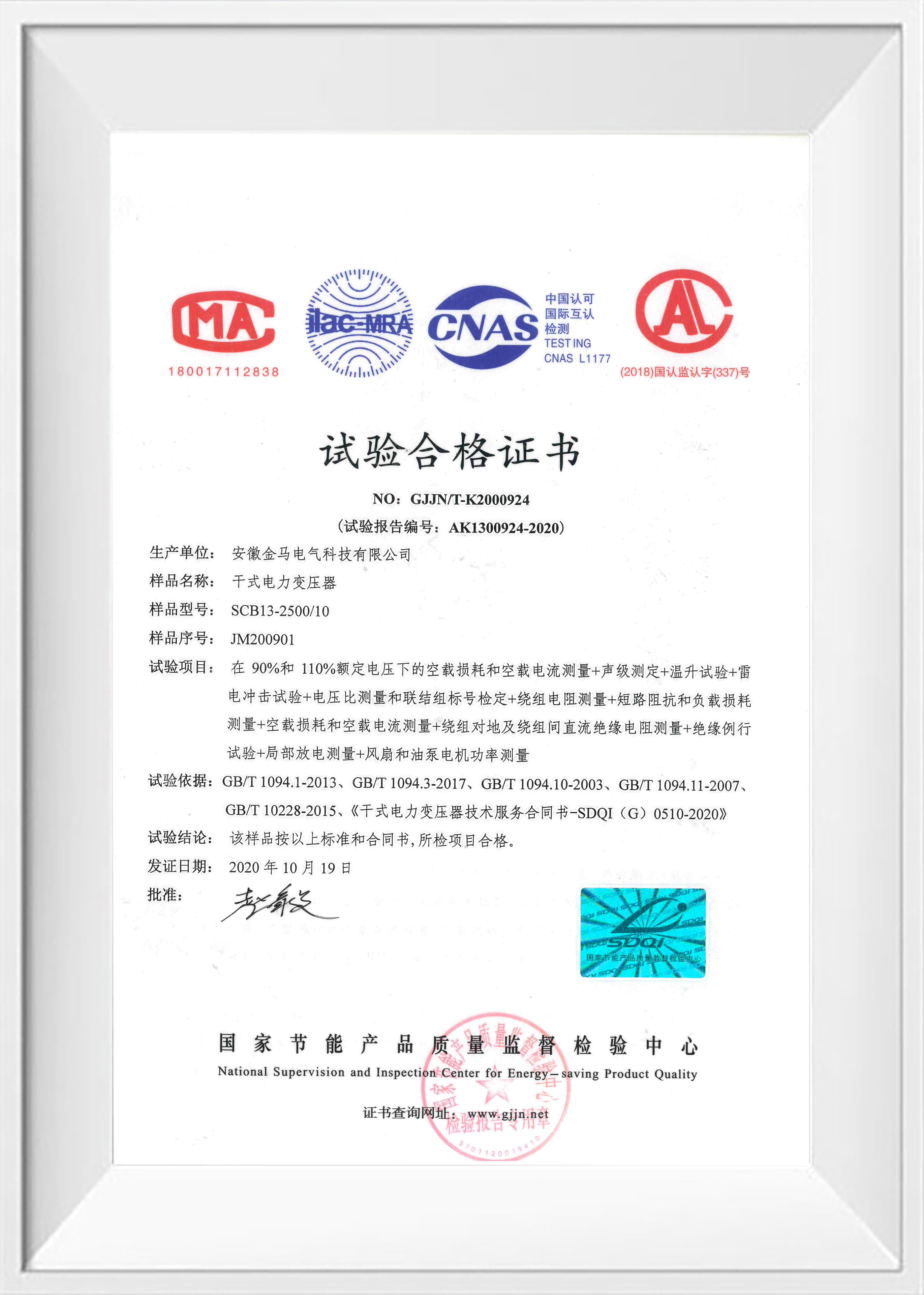
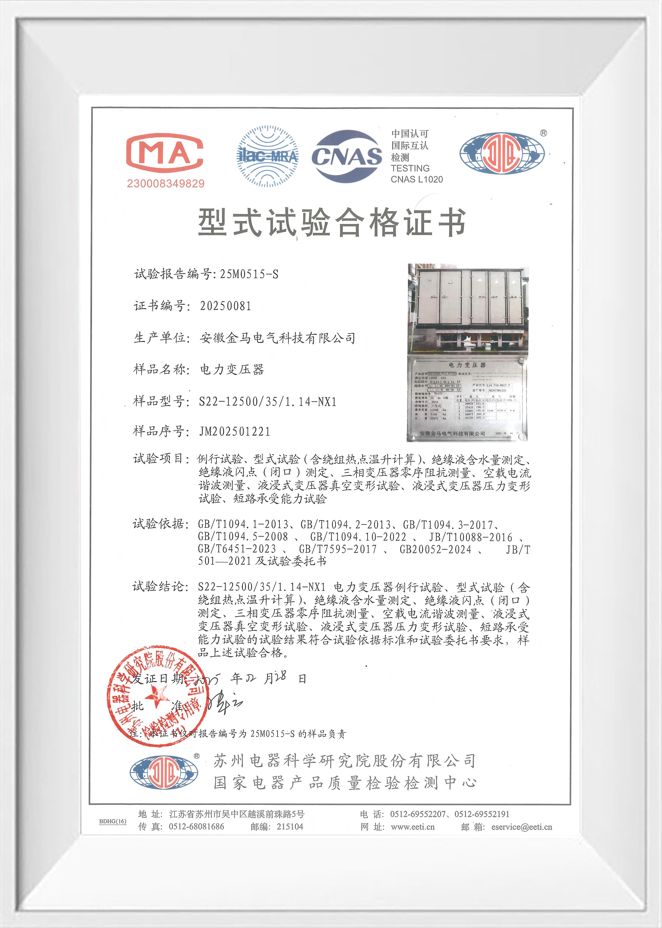
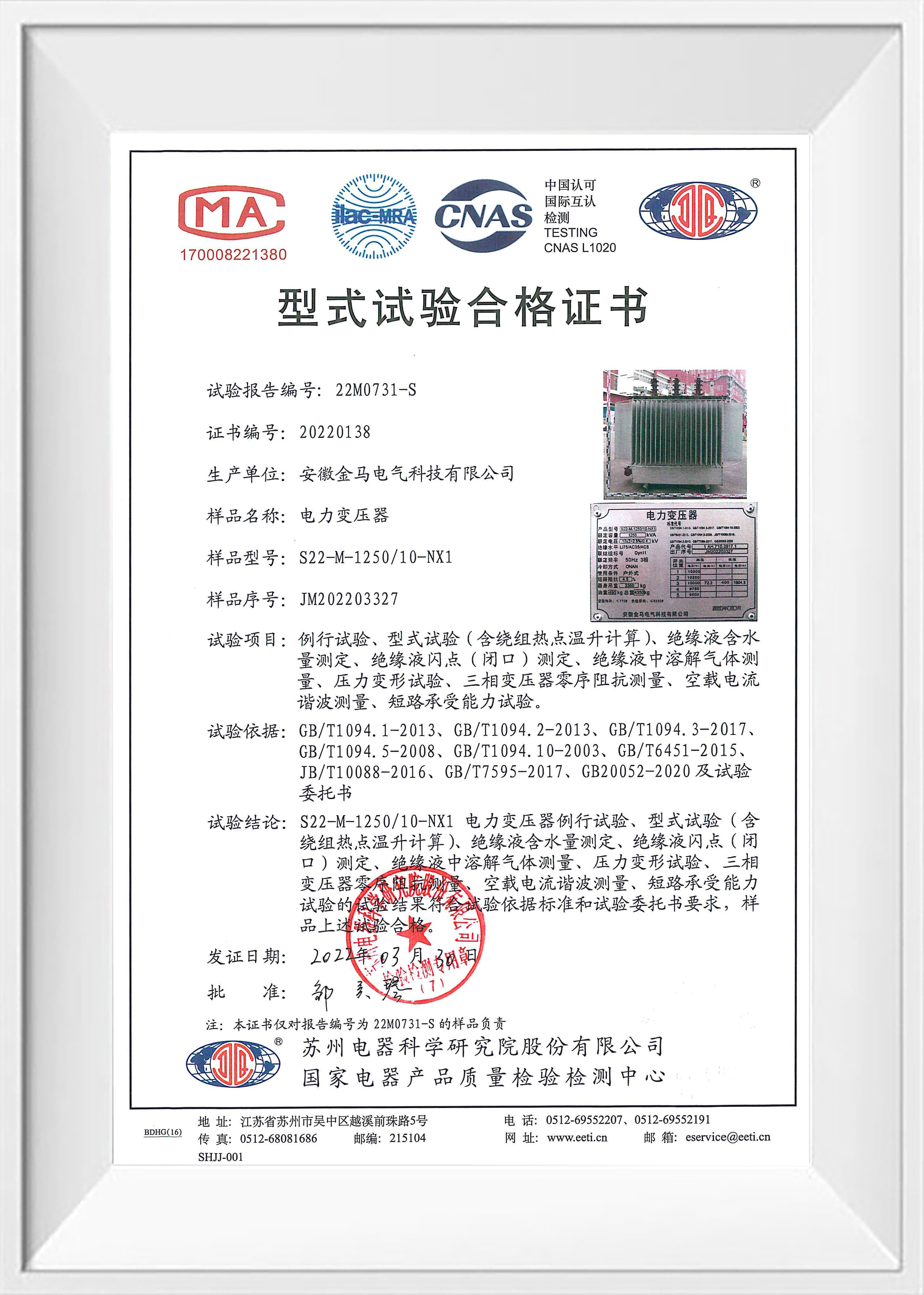
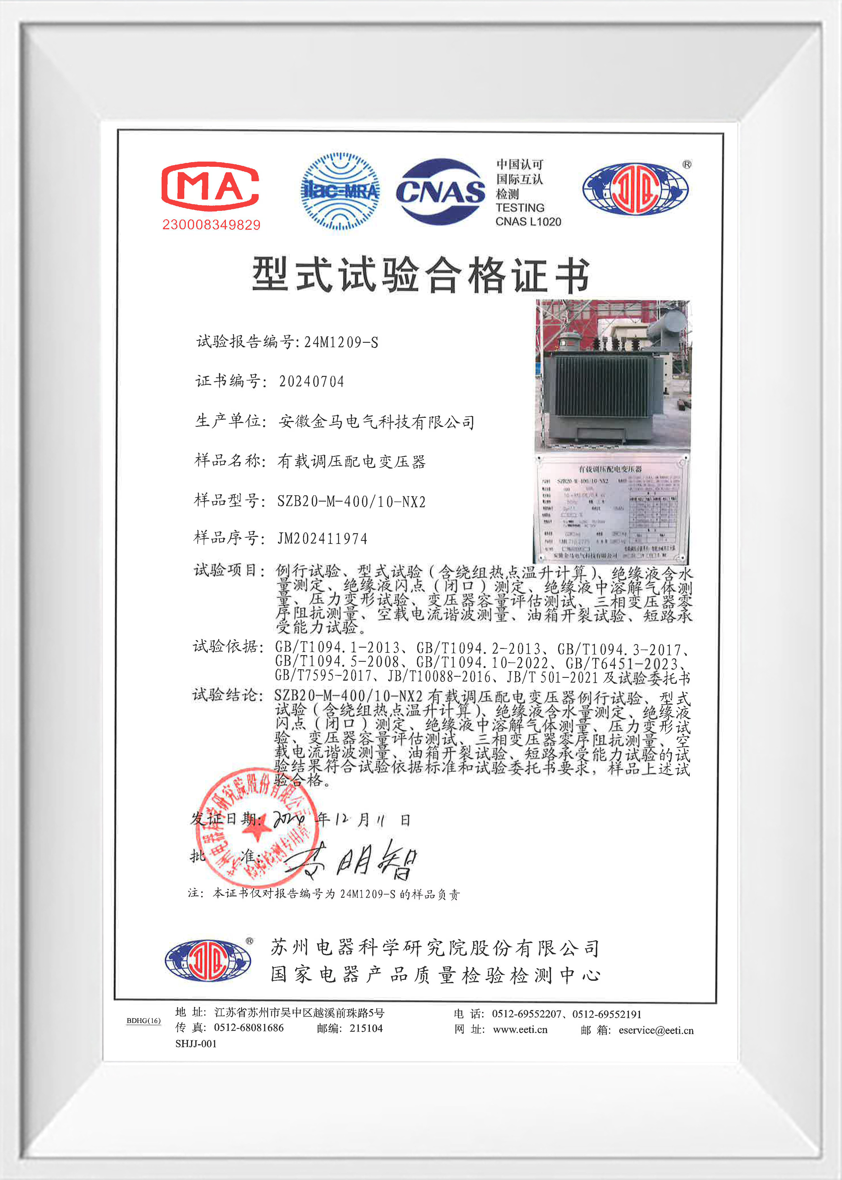
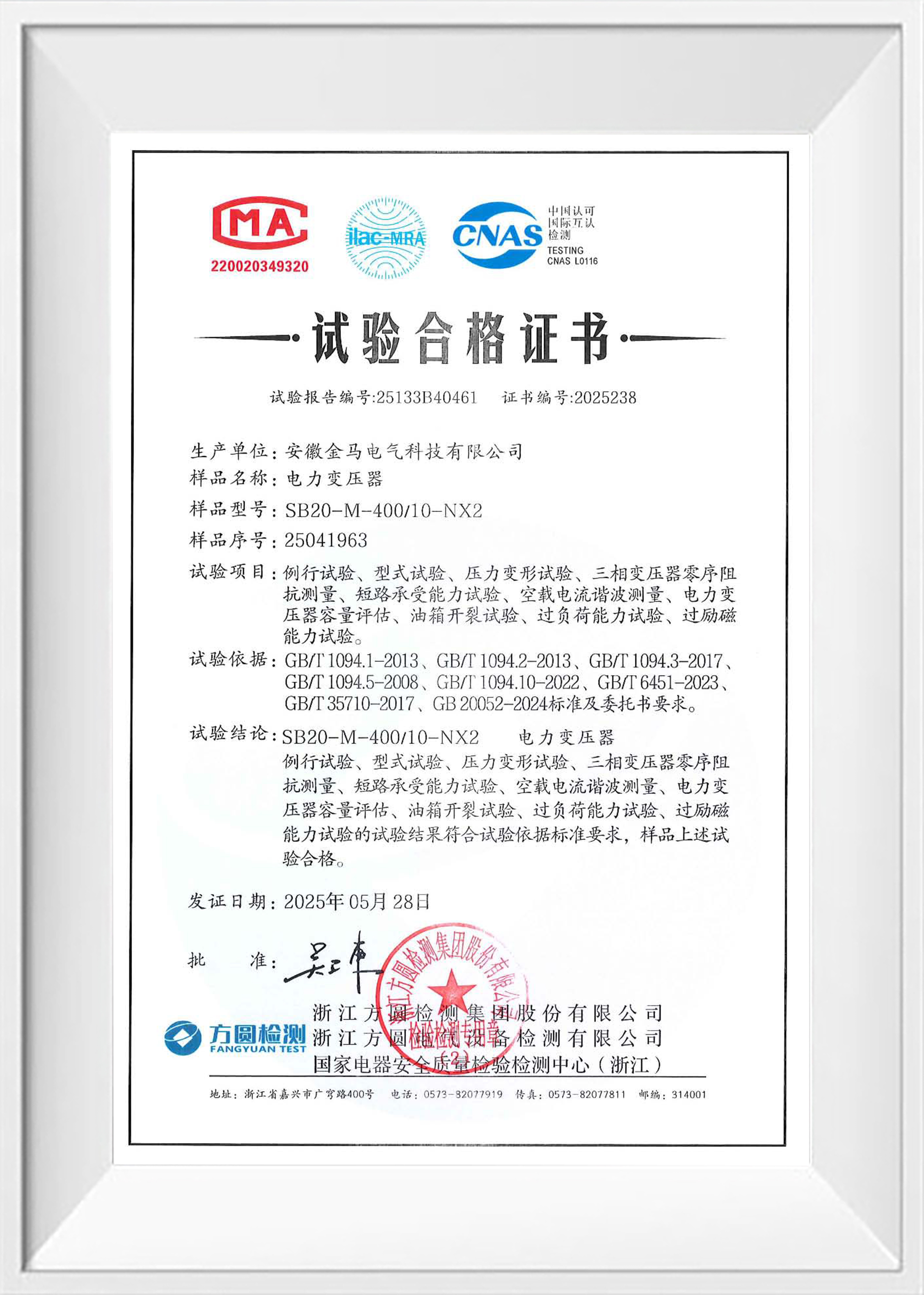
Who Are We
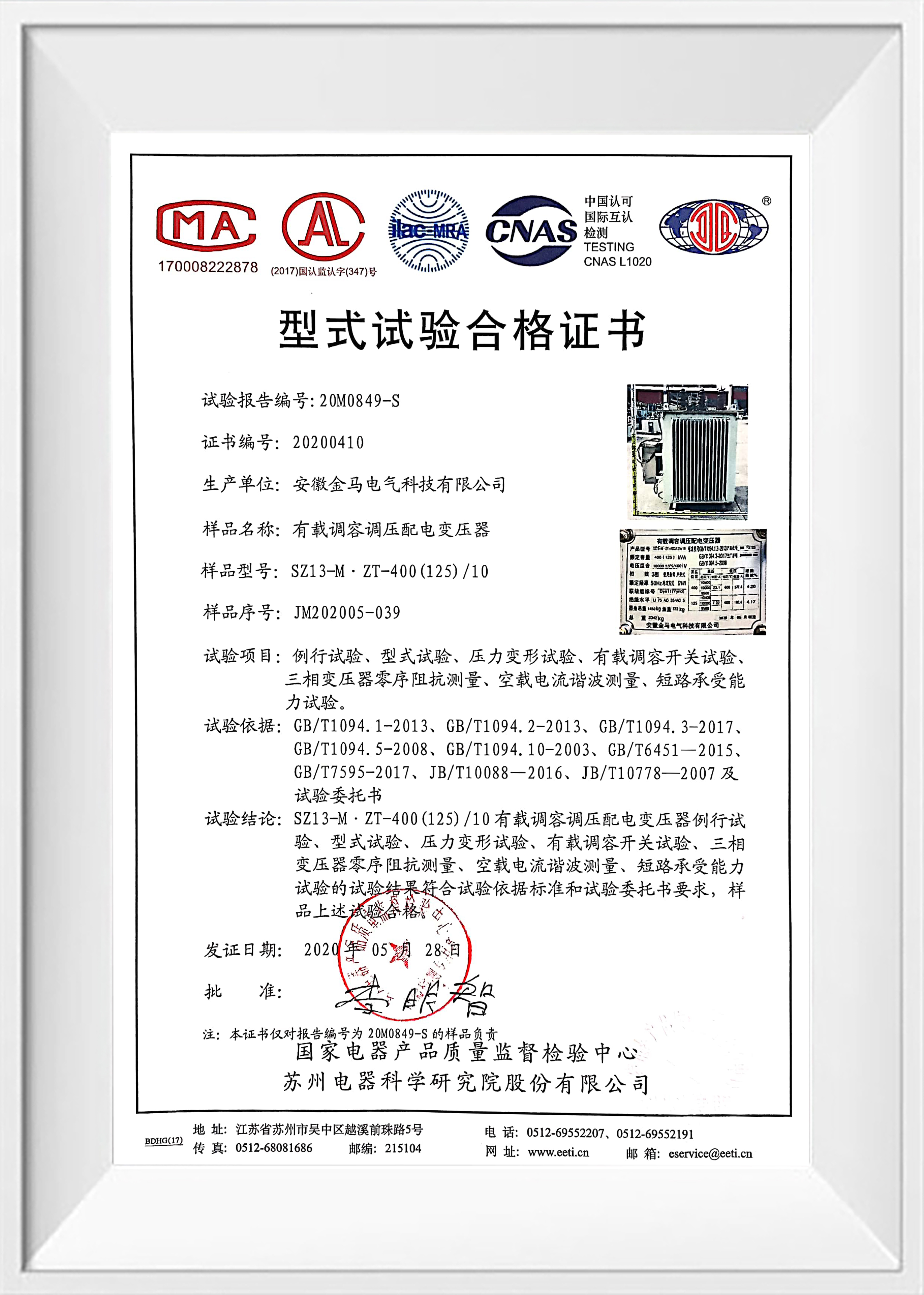
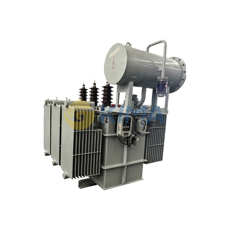
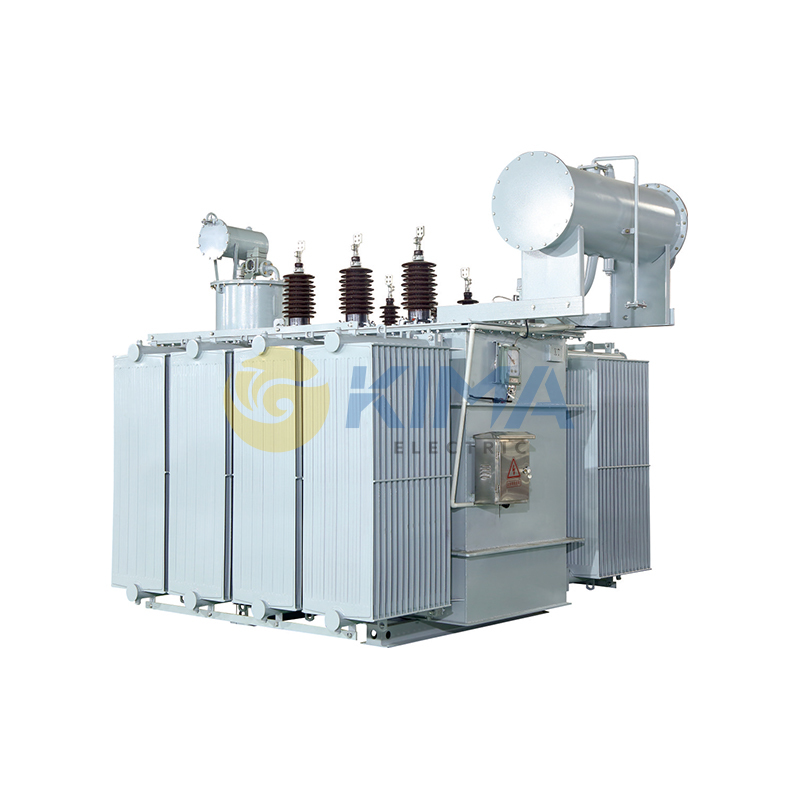
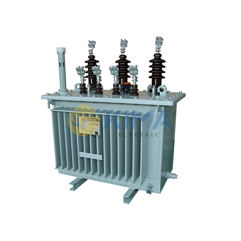
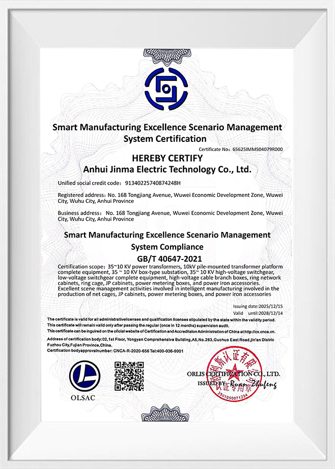
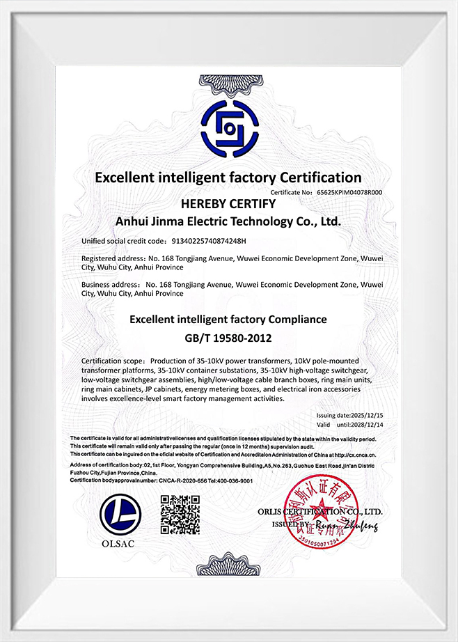
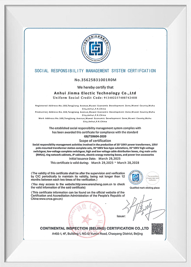
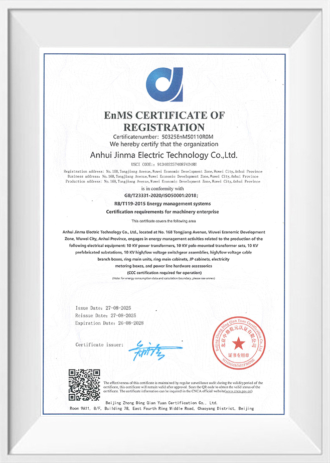
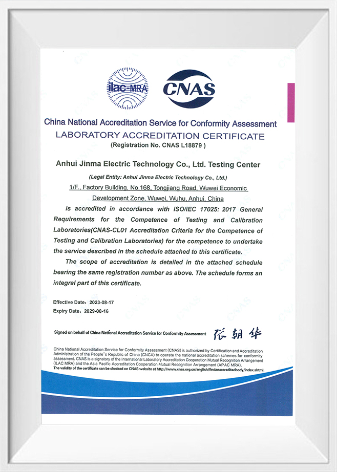
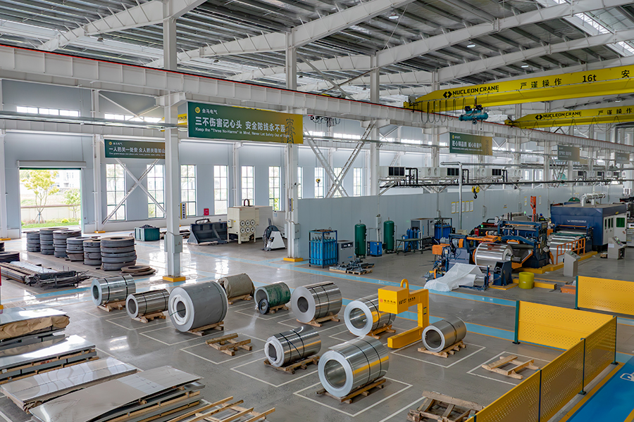
Kima Electric is a global brand under Anhui Jinma Electric Technology Co., Ltd.. and is a professional manufacturer of transformers &power transmission and distribution equipment in China. Established in 2001 and located in Wuwei, Wuhu City, Anhui Province, China ,the company occupies a facility spanning 93 mu (approximately 62,000 square meters) with a building area of 51,000 square meters and a professional team of over 180 personnel. With over 20 years of industry expertise, we have developed a comprehensive production system, rigorous quality control, and a culture of continuous innovation. We are committed to providing global customers with exceptional quality assurance and professional services.
-
0 +
Factory Area (㎡)
-
0 +
Employees
-
0 +
Industry Experience
-
0 +
Countries Sale


> KIMA, Your Trusted Global Partner
for Electrical Power Equipment <
Anhui Kima Electric Technology Co., Ltd.
-
 +86 400 0553 633
-
+86 199 4451 2191
-
 info@kimaelectric.com
-
 No. 168 Tongjiang Avenue, Wuwei Economic Development Zone, Wuwei City, Anhui Province, ChinaNote: Kima is a brand of Anhui Jinma Electric Technology Co., Ltd., China.
+86 199 4451 2191

PRODUCTS
RESOURCES
COMPANY LOCATION MAP
Copyright © Anhui Kima Electric Technology Co., Ltd. All Rights Reserved

-
 0
0
-
-
info@kimaelectric.com
-