info@kimaelectric.com
 +86 199 4451 2191




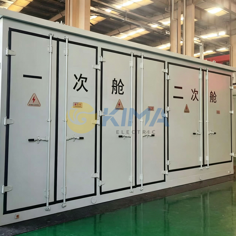
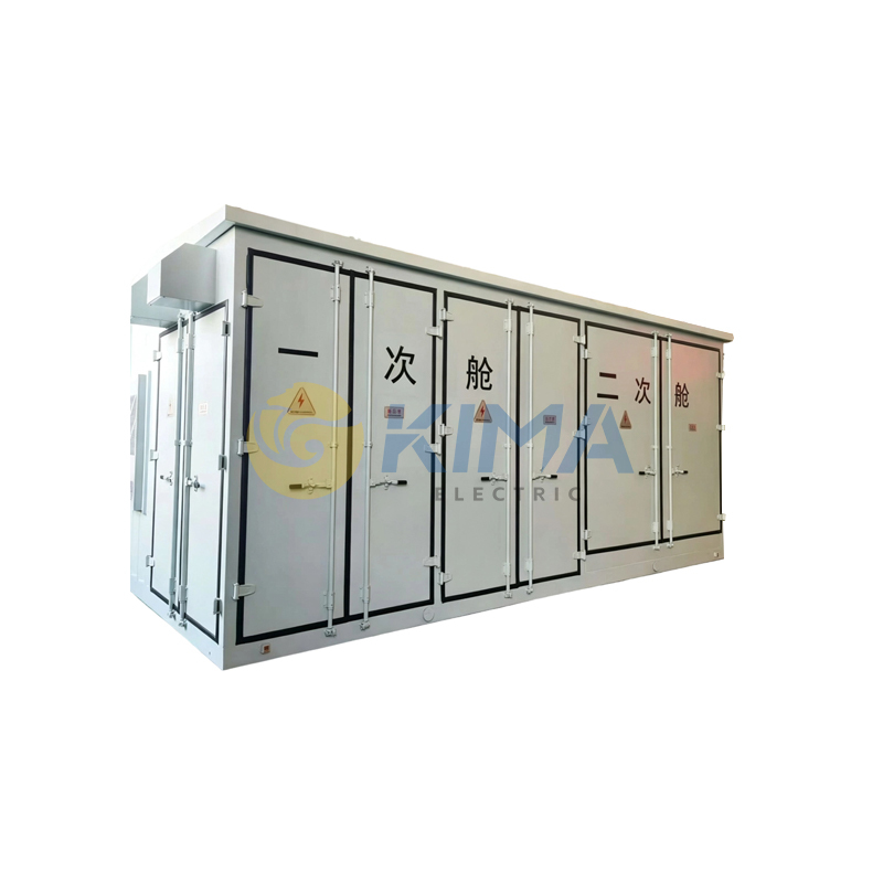
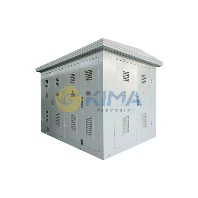
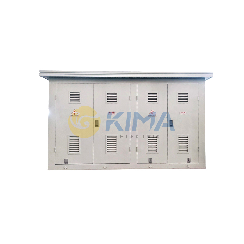
PV Prefabricated Substation
◆ Overview
We provide fully modular prefabricated solutions for substations, reducing the floor space by 30% and shortening the system design, installation, and commissioning cycles by 70%. The all-metal prefabricated enclosure is equipped with an intelligent environmental control system, making it suitable for complex climatic and geographical conditions such as high temperature, high humidity, and sandy dust. It supports access to the eCloud energy cloud platform, providing remote health diagnosis, fault analysis, maintenance guidance, and other functions, enabling unattended substation operation and full life cycle management of equipment. It features reliable operation and assured quality.
Technical Data
|
Rated HV Voltage |
Up to 40.5 kV |
|
Rated Power |
Up to 8000 kVA |
|
Rated Frequency |
50 or 60 Hz |
◆ Scope of Application
●Step-up substations for new energy sectors, including wind power generation, photovoltaic power generation, offshore wind power, and distributed photovoltaic power generation
●10kV-40.5kV grid substations
●Dedicated substations for large industrial and mining enterprises
◆ Service Environment
●Ambient temperature range: -40℃ to +85℃
●Installation site: Outdoor
●Altitude: Generally not exceeding 3000m
●Pollution class: Class III
●Outdoor wind speed: Not exceeding 35m/s
●Seismic resistance: Horizontal acceleration — 0.3m/s²
●Vertical acceleration — not exceeding 0.15m/s²
Should the above normal service conditions be exceeded, our company can provide customized designs according to specific user requirements.
◆ PV Prefabricated Substation vs. Conventional Substation
|
Item |
Conventional Outdoor Substation |
PV Prefabricated Substation |
|
Floor Space |
Approx. 3,000 m² |
Approx. 2,000 m² |
|
Construction Period |
Approx. 3-4 months |
The entire station is integrally pre-assembled, with equipment factory-prefabricated and only on-site installation required. Short construction period: 1-2 months. |
|
Cable Consumption |
Equipment is arranged in a dispersed manner, resulting in high consumption of primary and secondary cables. |
Equipment is highly integrated in layout, with shortened electrical distances, saving approximately 30% of cable usage. |
|
Environmental Requirements |
High environmental demands; equipment is significantly vulnerable to harsh conditions such as sandstorms and condensation. |
All-metal enclosure design with IP54 protection rating, equipped with a comprehensive HVAC system, providing protection against sandstorms and condensation, thereby enhancing equipment reliability. |
|
Construction and Management Costs |
Multiple buildings result in high construction costs; equipment is supplied by various manufacturers, leading to high coordination and management costs. |
Prefabricated design eliminates buildings throughout the station, resulting in low construction costs. All equipment is supplied by our company, which is responsible for complete installation and commissioning, ensuring low management costs. |
|
Operation and Maintenance Costs |
Open-type design is significantly affected by environmental conditions, resulting in high operation and maintenance costs. |
Enclosed design is largely unaffected by external environmental conditions, resulting in low operation and maintenance costs. |
◆ Centralized Photovoltaic Power Station — Network Topology Diagram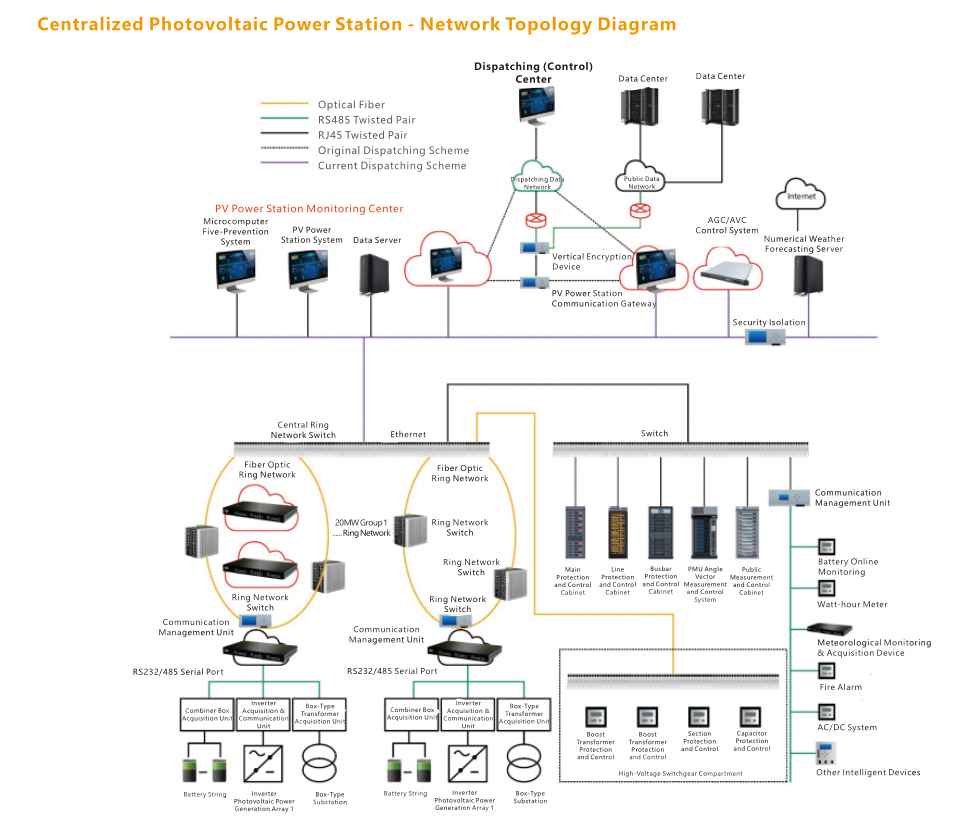
◆ Typical Technical Solutions and Product Configuration
|
No. |
Main Equipment Name |
Basic Configuration |
|
I |
Monitoring System |
|
|
1 |
Background Monitoring System |
Including monitoring host, display, speakers, and various software configurations |
|
2 |
Five-Prevention Monitoring System |
Including five-prevention software, lock sets, etc. |
|
II |
Telecontrol & Public Measurement System |
|
|
1 |
Telecontrol Communication Panel |
Including telecontrol equipment, intelligent interface device, time synchronization device, etc. |
|
2 |
Public Measurement and Control Panel |
Including public measurement and control device, power quality monitoring device, network switch, etc. |
|
3 |
Synchrophasor Measurement Panel |
Including phasor measurement and control device, etc. |
|
4 |
Busbar Protection Panel |
Including busbar protection device, etc. |
|
5 |
Security Automatic Device Panel |
Including frequency-voltage sectionalizing device, anti-islanding protection device, etc. |
|
6 |
Optical Power Prediction Panel |
Including optical power prediction server, reverse isolation device, etc. |
|
7 |
Active & Reactive Power Control Panel (AGC/AVC) |
Including AGC/AVC device system, firewall, etc. |
|
8 |
Fault Recorder Panel |
Including fault recorder device, etc. |
|
III |
Power Supply System |
|
|
1 |
Dual-Power AC Incoming Panel |
Including ATS and Class 0.5 watt-hour meter |
|
2 |
AC Feeder Panel |
Including feeder switches, etc. |
|
3 |
DC Charging Panel |
Subject to specific configuration |
|
4 |
DC Feeder Panel |
Including feeder switches, etc. |
|
5 |
Battery Panel |
80AH / 100AH |
|
6 |
UPS Power Panel |
3kVA |
|
IV |
Communication System |
|
|
1 |
Dispatching Data Network Panel |
Including access router, access switch, vertical encryption authentication device, hardware firewall, IDS intrusion detection device, etc. |
|
2 |
Network Communication Cabinet |
Including SDH equipment, PCM equipment, etc. |
|
3 |
Integrated Distribution Frame Panel |
Including corresponding ODF, etc. |
|
4 |
Electrical Energy Data Acquisition Terminal |
Installed in the metering panel cabinet |
|
V |
Distributed Installation Equipment |
|
|
1 |
Fiber Differential Protection and Control Device |
Subject to specific project configuration |
|
2 |
Line Protection and Control Device |
Subject to specific project configuration |
|
3 |
SVG Protection and Control Device |
Subject to specific project configuration |
|
4 |
Station Transformer Protection & Control Device |
Subject to specific project configuration |
|
5 |
Power Quality Monitoring Device |
Subject to specific project configuration |
|
6 |
Smart Watt-hour Meter |
Subject to specific project configuration |
|
VI |
PV Farm Area |
|
|
1 |
Box Transformer Measurement and Control Device |
Subject to specific project configuration |
|
VII |
Video Surveillance System |
|
|
1 |
Video Surveillance System |
Including cameras, video server, display, etc. |
|
VIII |
Fire Alarm System |
|
|
1 |
Fire Alarm System |
Including smoke detectors, manual alarm call points, audible and visual alarms, fire alarm host, etc. |
Please provide the following accurate information when requesting a quotation or placing an order, so that we can perform technical calculations and schedule production accordingly:
Project Overview:
Project name, installation site, and operating environment (e.g., altitude, extreme maximum/minimum temperatures, annual average temperature, maximum wind speed, seismic fortification intensity, relative humidity, maximum frozen soil/snow depth, pollution level, and presence of corrosive gases, etc.).
Product Model & Specifications:
Specify the type of prefabricated cabin required (e.g., primary equipment cabin, secondary equipment cabin, energy storage battery cabin, etc.), as well as internal clear dimensions (L×W×H). Preliminary dimensions are subject to final approved drawings.
Transformer Configuration:
Transformer Type: Oil-immersed transformer / Dry-type transformer
Rated Capacity (kVA)
Primary & Secondary Voltage Levels (e.g., 12kV / 0.4kV)
Rated Frequency (50Hz or 60Hz)
Winding Material: Copper windings or Aluminum windings
Cabin Structure & Materials:
Frame Material: High-quality carbon structural steel (yield strength requirement, e.g., ≥235 MPa).
Steel Plate Thickness: Specify thickness standards for frame, doors, roof, and floor (e.g., frame ≥2.5 mm, floor ≥3 mm).
Roof & Floor: Roof style (e.g., double-slope roof with pitch requirements), thermal insulation material, height and material of anti-static raised access floor.
Appearance & Corrosion Protection:
Specify exterior color (provide color card number or RAL code), corrosion protection grade, and design standards for anti-condensation and water accumulation prevention.
Protection Levels:
Specify overall IP rating of the cabin and external mechanical impact resistance level (e.g., IK10).
Key Technical Parameters & Configuration Requirements
●Auxiliary System Configuration:
●HVAC & Temperature Control: Specify air conditioning system configuration (quantity, power), ventilation, heating, and forced-air cooling requirements.
●Fire Safety: Fire and smoke alarm systems (including relay output alarms), dry powder/gas fire extinguisher configuration, and explosion-proof emergency lighting requirements.
●Lighting & Electrical: LED lighting system inside the cabin, power sockets, maintenance aisle lighting, and cable routing requirements.
Intelligent Systems & Monitoring:
Specify pre-installed conduits for video surveillance systems, remote terminal unit (DTU/FTU) configuration, and communication interface requirements (e.g., RS485, Ethernet, Modbus protocol, etc.).
Sealing & Cable Entry/Exit:
Specify knockout hole sizes for HV/LV cable entry/exit, multi-diameter sealing component configuration, and connection method with cable trenches/cable trays.
Special Functional Requirements:
If special anti-condensation devices, environmental monitoring systems, or other customized auxiliary facilities are required, please specify in writing in advance.
Ordering Process & Important Notes
Technical Agreement Execution:
For non-standard products or complex projects, both parties must sign a detailed Prefabricated Cabin Technical Agreementprior to production scheduling. This agreement shall define the scope of supply, list of auxiliary system equipment, and acceptance criteria, and shall have the same legal effect as an annex to the contract.
Drawing Confirmation:
We will provide detailed layout drawings, foundation drawings, and primary/secondary system diagrams based on your requirements. Please sign and confirm these drawings promptly. Any schedule delays resulting from late confirmation shall be borne by your side.
Change Management:
After order confirmation and signed drawings, any technical or commercial changes must be submitted in writing and reconfirmed by both parties. Any cost increases or schedule delays arising from such changes shall be borne by the initiating party.
Site Coordination:
Please ensure that on-site foundation construction strictly follows our foundation drawings and that adequate access is reserved for lifting, assembly, and transportation. If you require our on-site assembly guidance, installation & commissioning services, or personnel training, please schedule in advance.
If you are looking for reliable power support for your project, please contact the Kima Electric team. We are ready to provide you with the best solutions.
◆ Convenient Inquiry Process
You may contact us through various channels, including our website and email. You can also download and fill out the "Inquiry Request Form" from our official website, or directly provide your existing technical documents and drawings as the basis for requirement assessment. We will provide a quotation as soon as possible.
◆ Production & Quality Control
- Prior to formal production, we will provide detailed technical proposals including specifications and structural drawings for your review and confirmation.
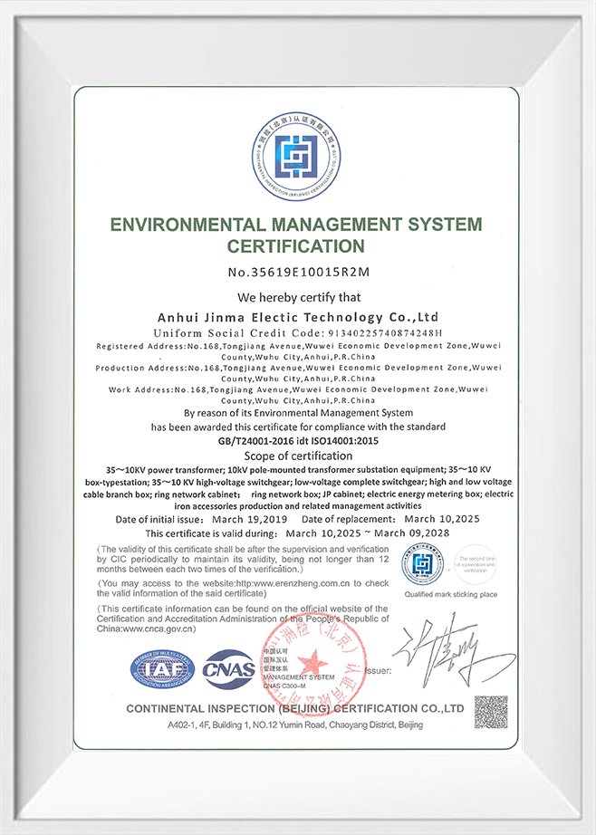
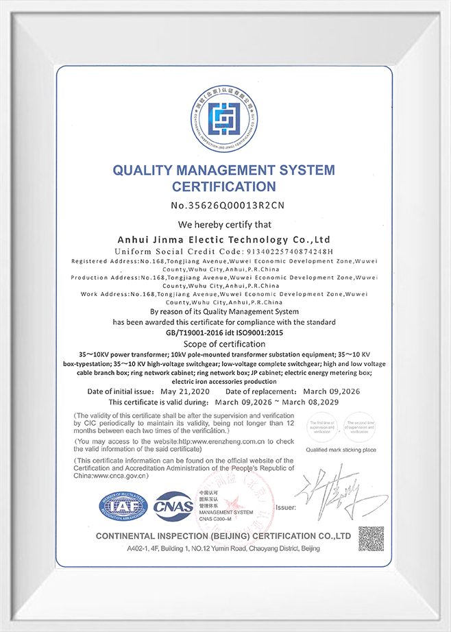
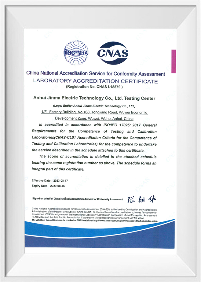
- We strictly implement the ISO quality management system, with comprehensive monitoring of raw materials, production processes, and finished product inspections to ensure stable and reliable quality for every customized product.
◆ Delivery & After-Sales Service
- Packed in specialized wooden crates compliant with international standards, lined with high-performance moisture-proof materials to ensure absolute safety and dryness during long-distance transportation.
- Detailed user manuals, maintenance manuals, and related documentation are provided with each shipment.
- Remote or on-site installation guidance and commissioning services are available upon request.
- Comprehensive after-sales support including technical consultation, troubleshooting, and spare parts supply to ensure long-term stable operation.
Who Are We
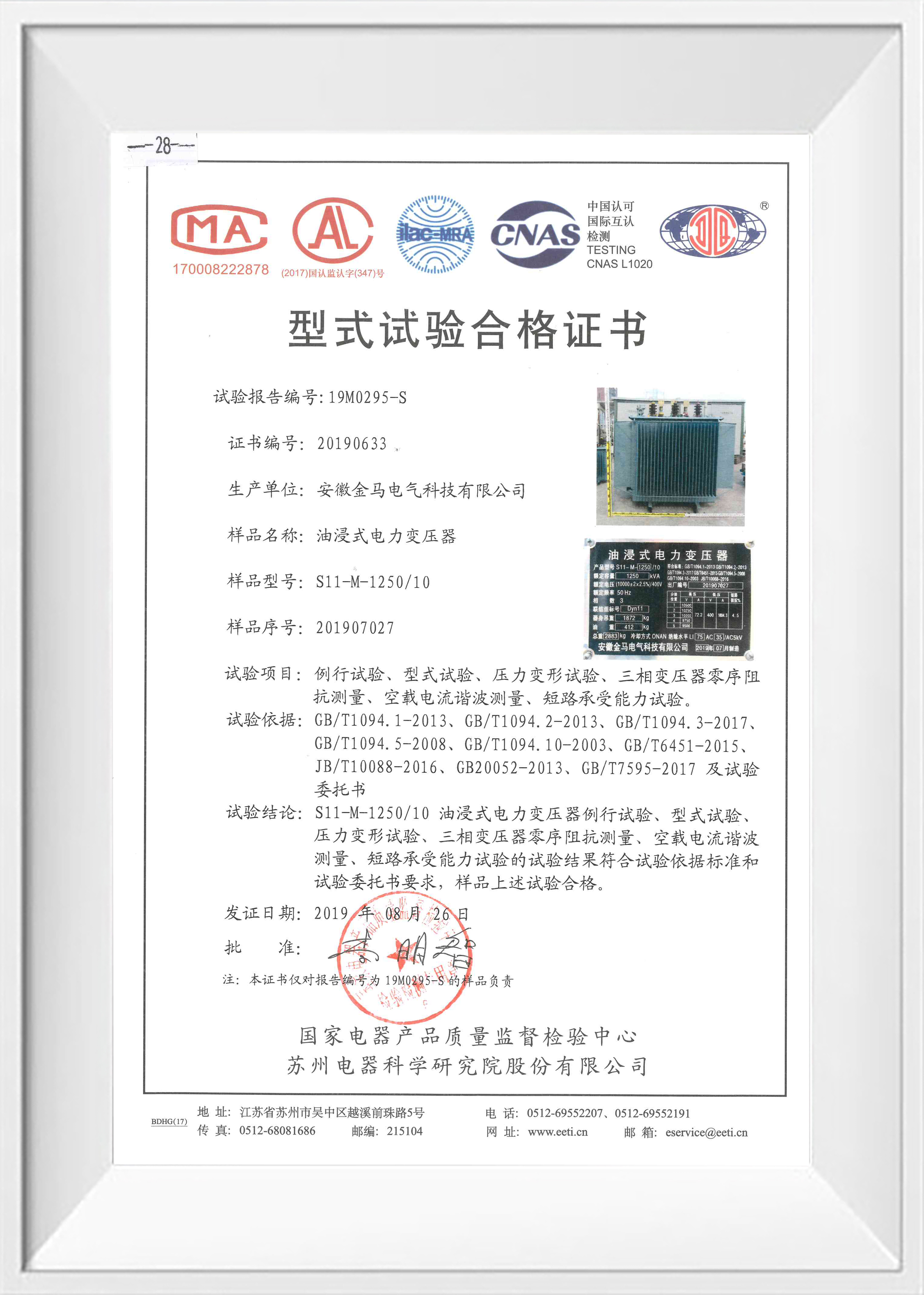
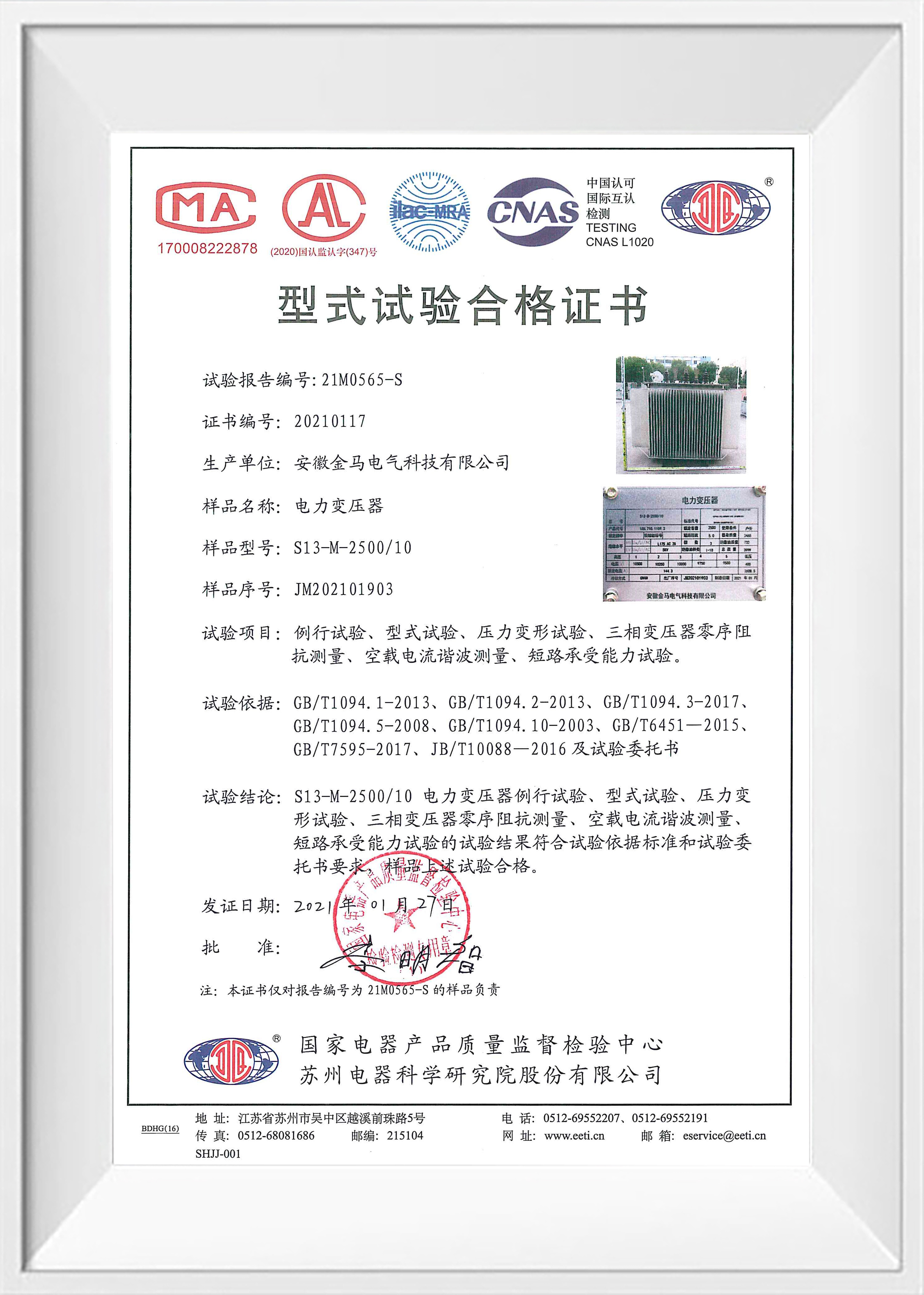
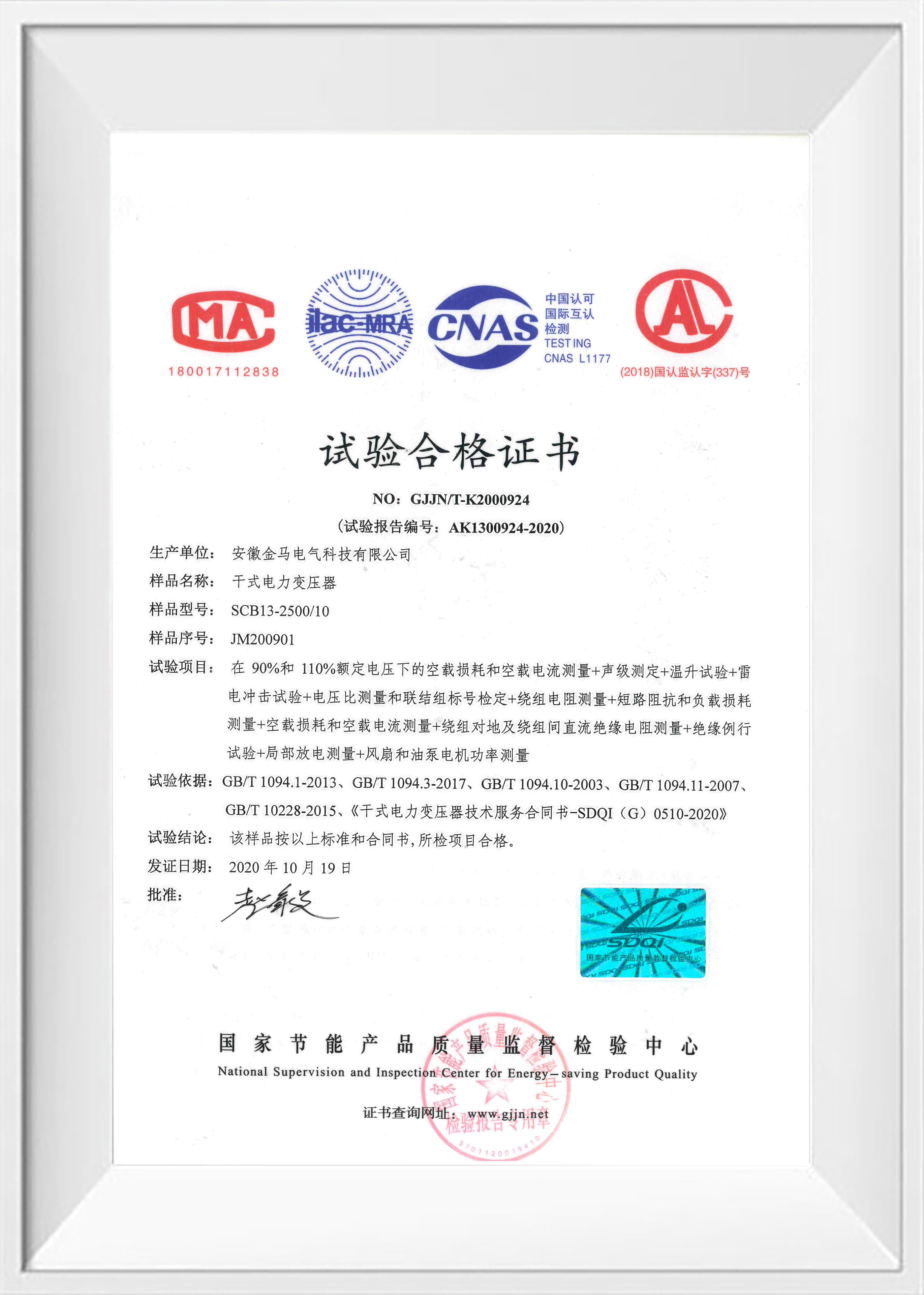
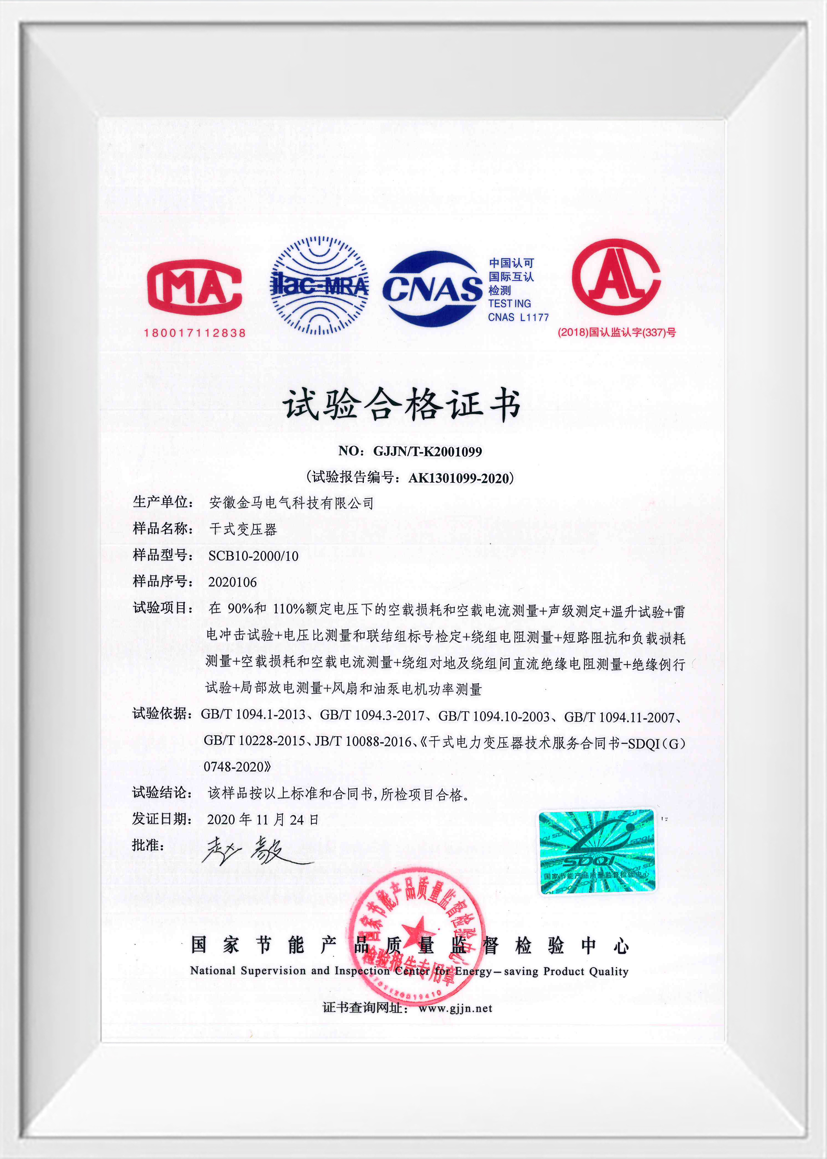
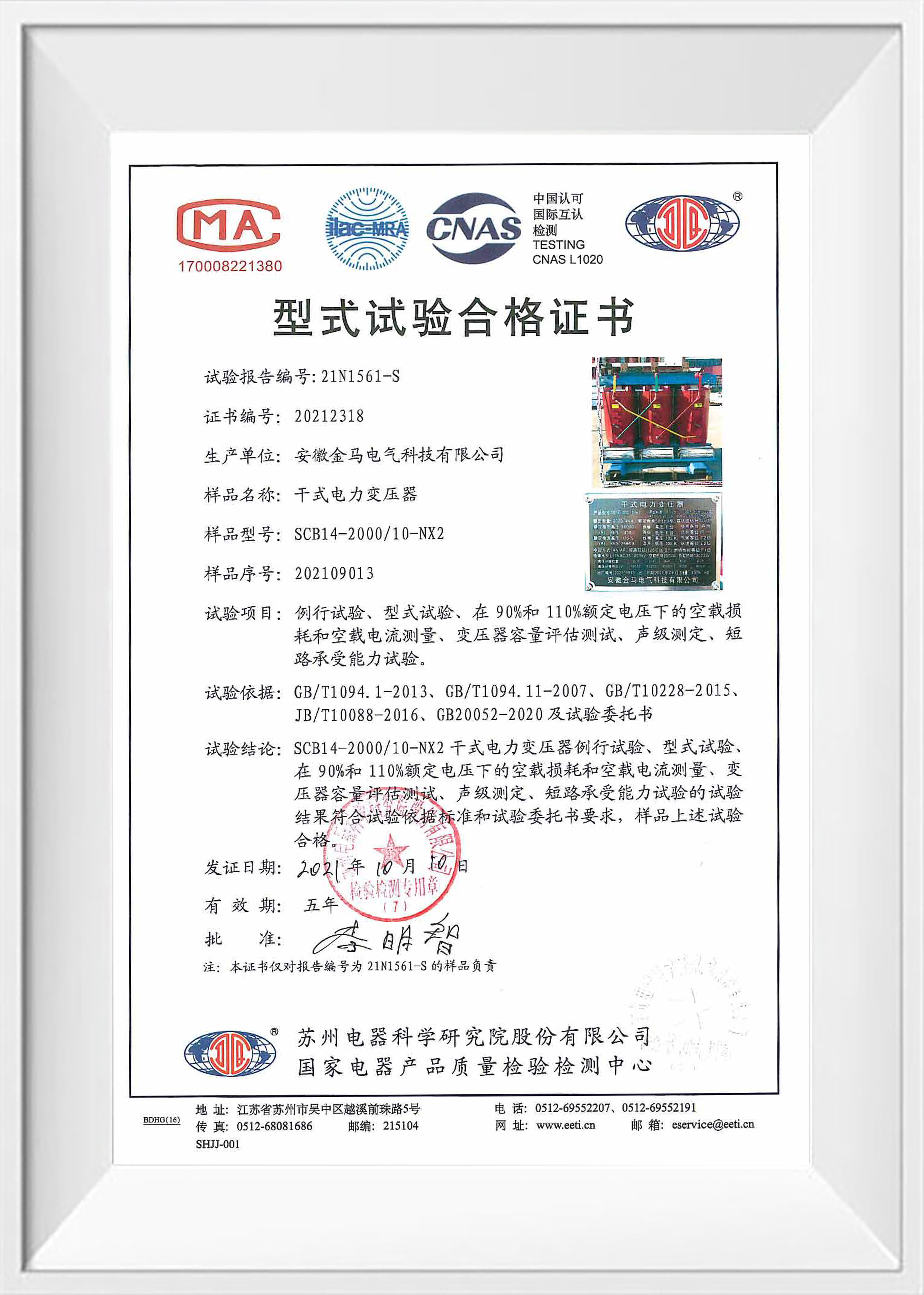
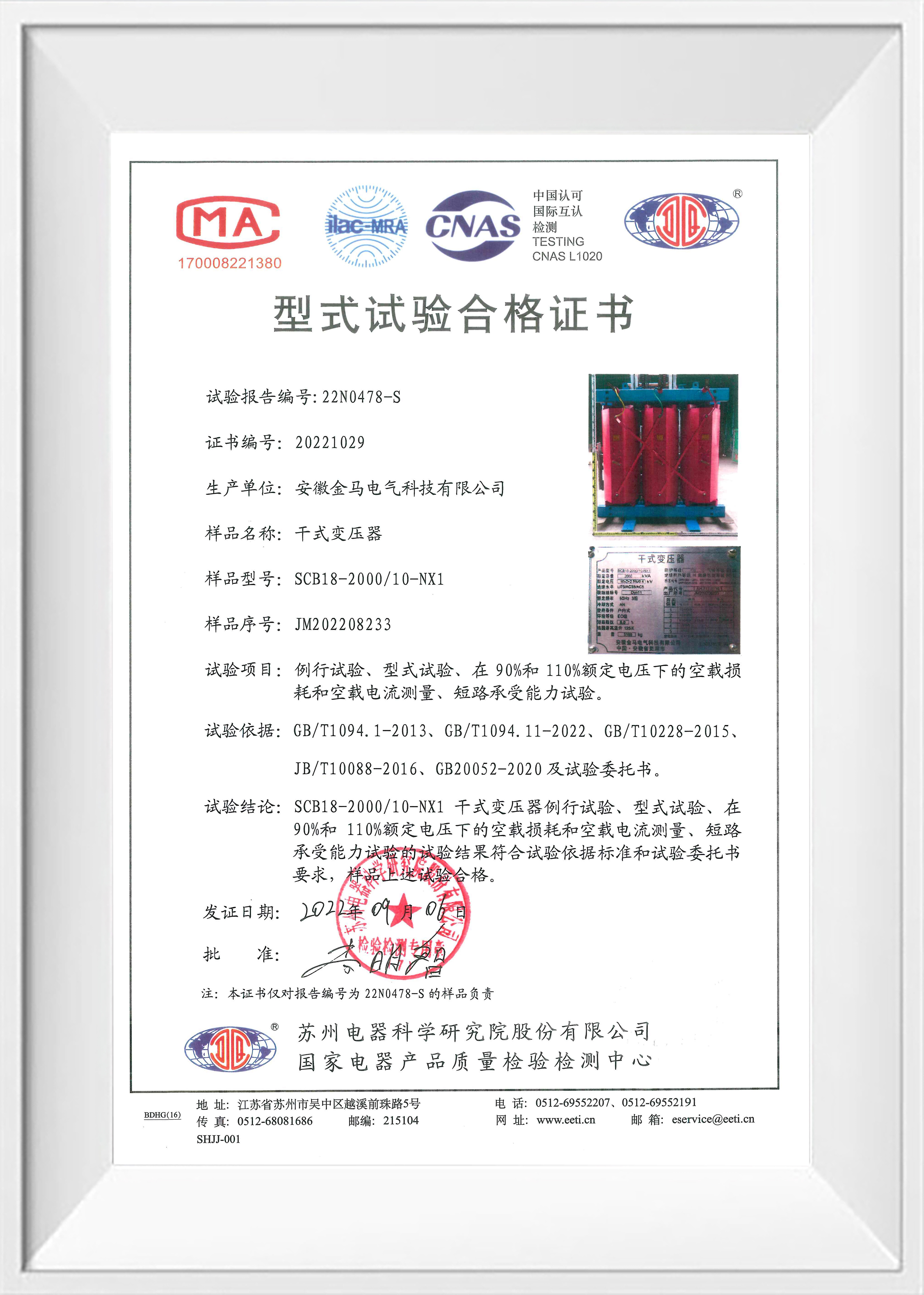
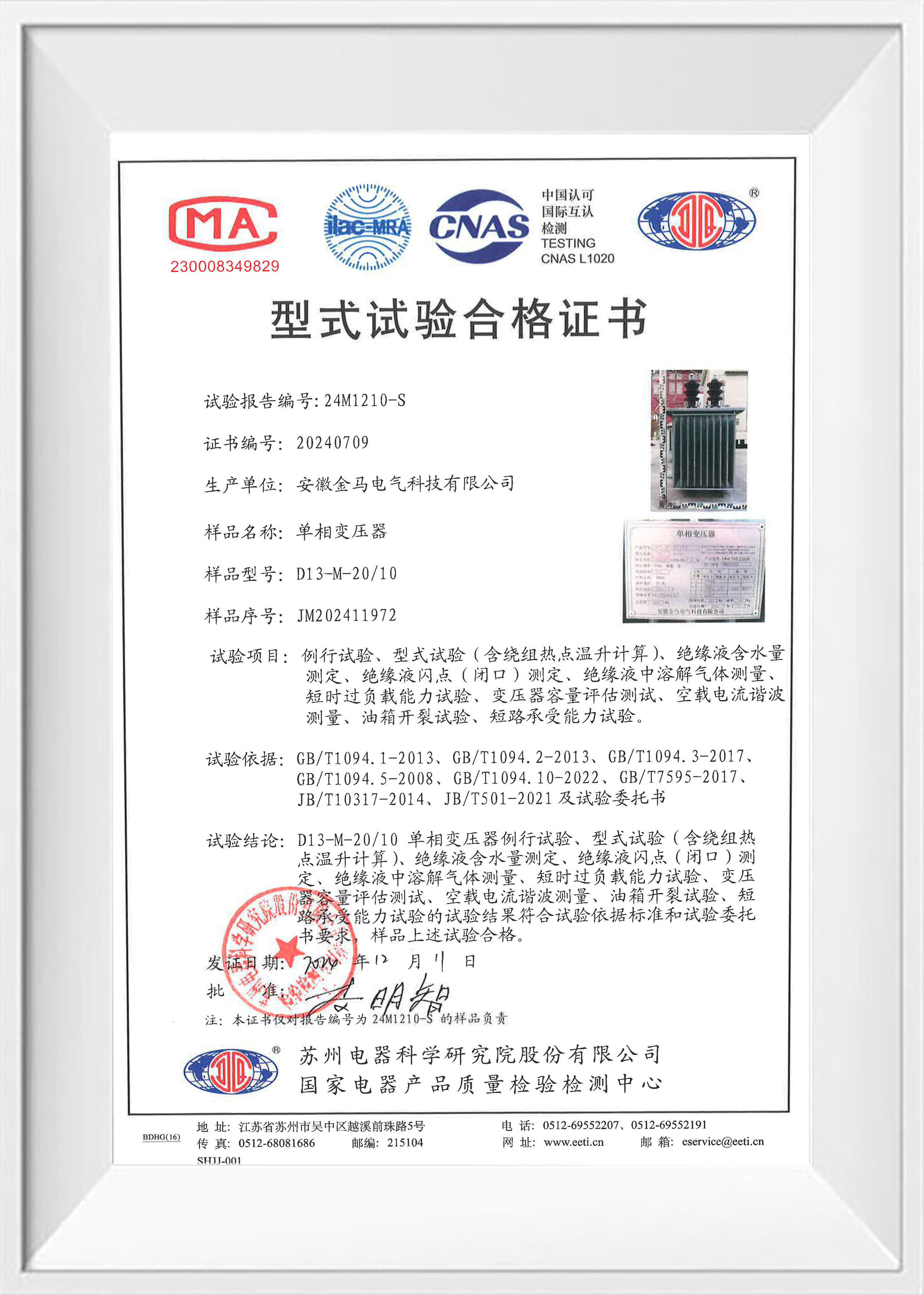
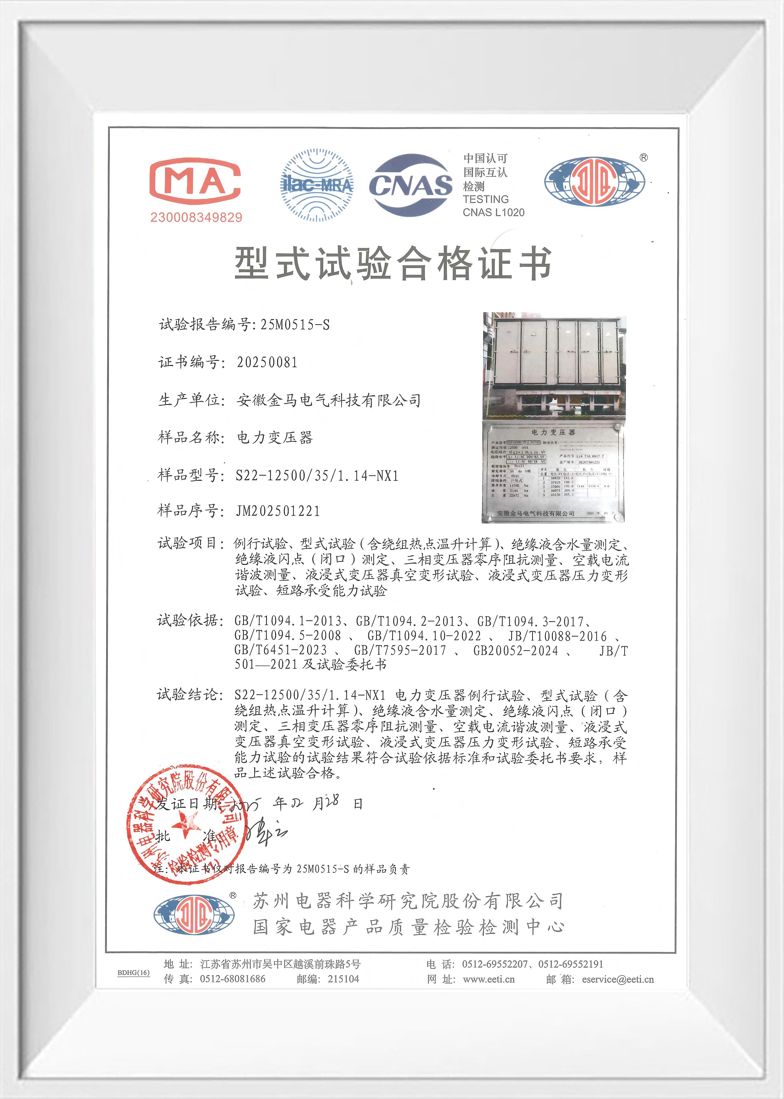
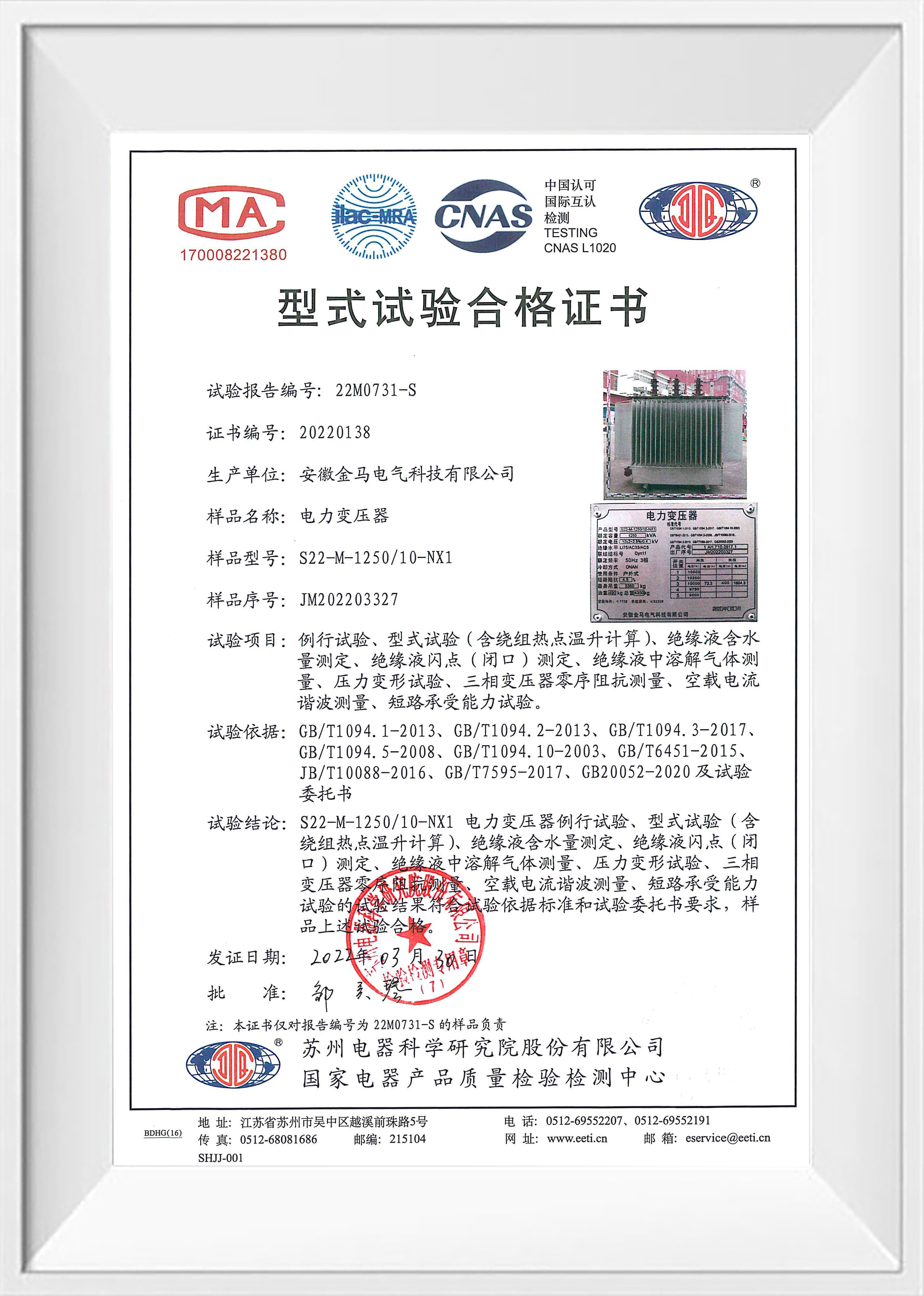
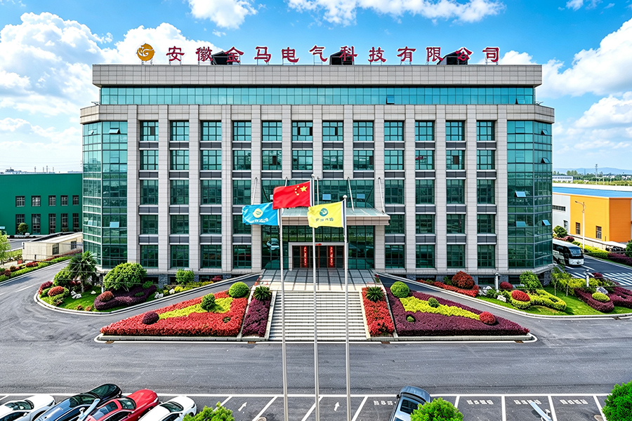
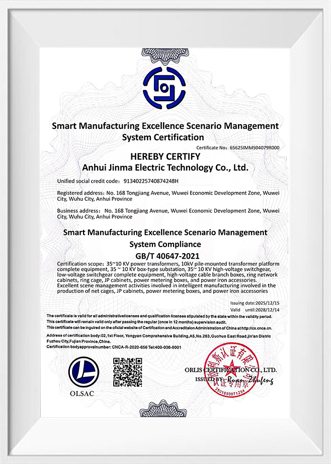
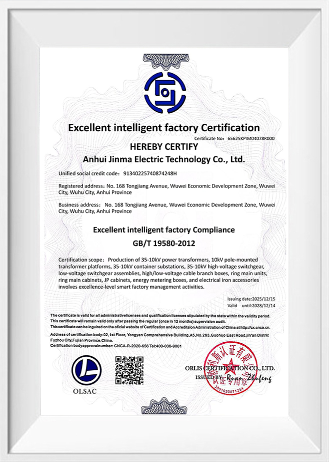
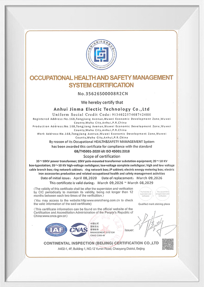
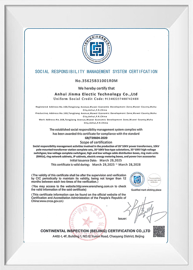
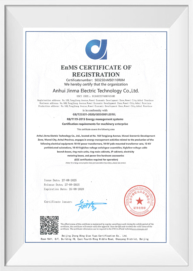
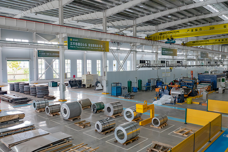
Kima Electric is a global brand under Anhui Jinma Electric Technology Co., Ltd.. and is a professional manufacturer of transformers &power transmission and distribution equipment in China. Established in 2001 and located in Wuwei, Wuhu City, Anhui Province, China ,the company occupies a facility spanning 93 mu (approximately 62,000 square meters) with a building area of 51,000 square meters and a professional team of over 180 personnel. With over 20 years of industry expertise, we have developed a comprehensive production system, rigorous quality control, and a culture of continuous innovation. We are committed to providing global customers with exceptional quality assurance and professional services.
-
0 +
Factory Area (㎡)
-
0 +
Employees
-
0 +
Industry Experience
-
0 +
Countries Sale

> KIMA, Your Trusted Global Partner
for Electrical Power Equipment <
Anhui Kima Electric Technology Co., Ltd.
-
 +86 400 0553 633
-
+86 199 4451 2191
-
 info@kimaelectric.com
-
 No. 168 Tongjiang Avenue, Wuwei Economic Development Zone, Wuwei City, Anhui Province, ChinaNote: Kima is a brand of Anhui Jinma Electric Technology Co., Ltd., China.
+86 199 4451 2191

PRODUCTS
RESOURCES
COMPANY LOCATION MAP
Copyright © Anhui Kima Electric Technology Co., Ltd. All Rights Reserved

-
 0
0
-
-
info@kimaelectric.com
-