info@kimaelectric.com
 +86 199 4451 2191




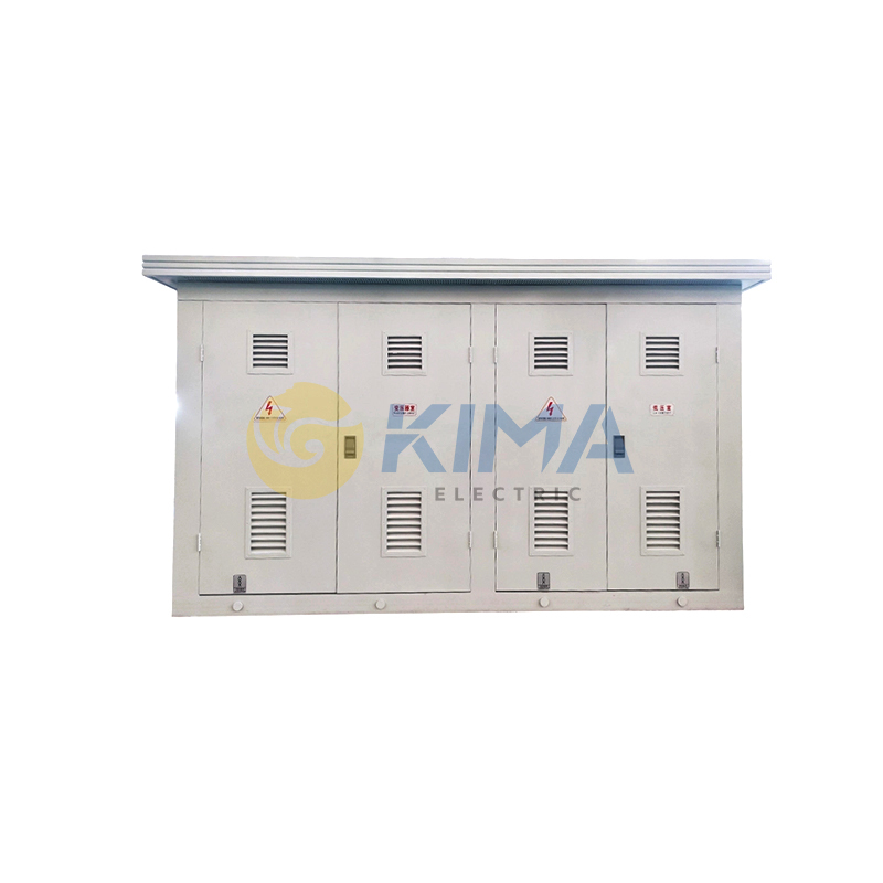
PV Booster Station
Overview
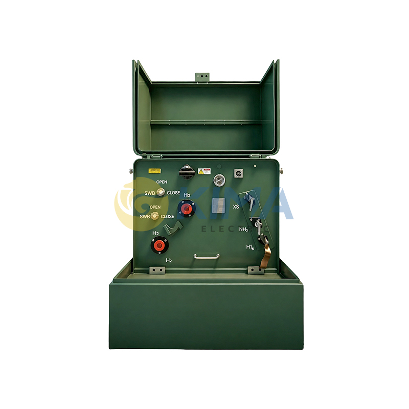
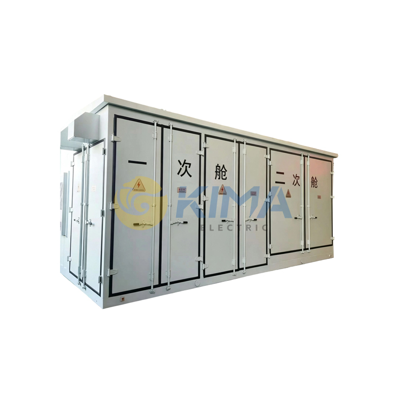
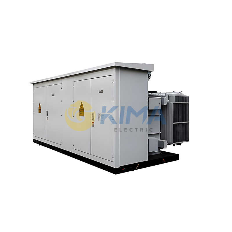
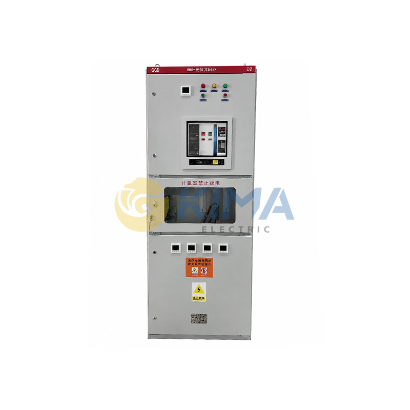
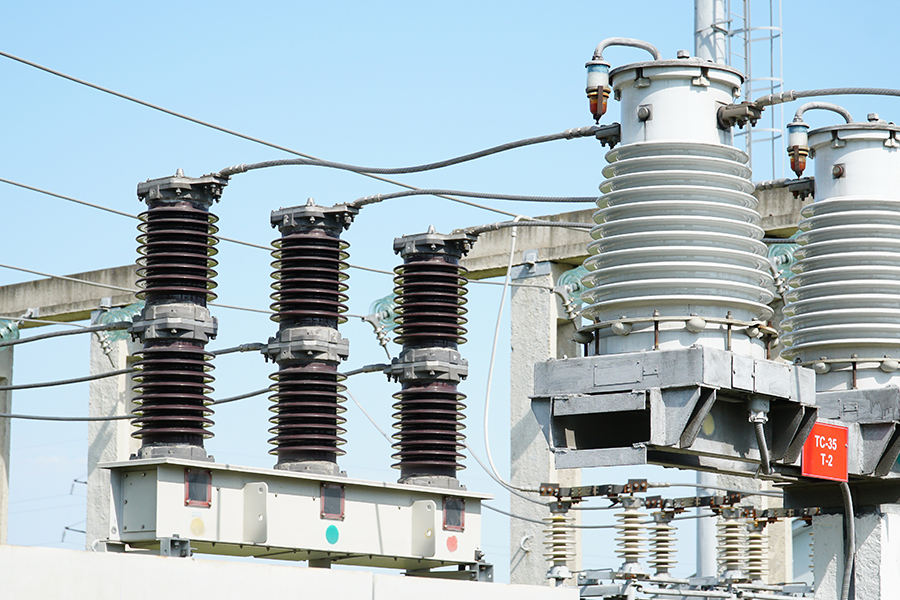
The PV Booster Station is an outdoor integrated step-up solution designed specifically for large-scale ground-mounted PV power plants and commercial & industrial (C&I) distributed PV projects. It integrates core equipment including medium-voltage switchgear, step-up transformers, low-voltage distribution panels, automation control systems, reactive power compensation devices, and environmental monitoring systems into one or more standardized container-type cabins.
Adopting a factory-preassembled, modular design, the product offers significant advantages including high reliability, intelligent operation and maintenance, flexible deployment, and plug-and-play functionality. It substantially shortens project construction cycles, reduces on-site installation complexity and costs, and ensures the safe, stable, and efficient integration of PV systems into the medium-voltage grid.
Technical Specifications
|
Rated Voltage |
Up to 35 kV |
|
Rated Current |
Up to 1250 A |
|
Rated Frequency |
50Hz / 60Hz |
Normal Operating Environment
Altitude: ≤ 2000 m (derating required above 2000 m)
Ambient Temperature: -40°C ~ +55°C (operating); -45°C ~ +70°C (storage)
Relative Humidity: 5% ~ 95% (non-condensing)
Protection Class: Cabin IP54 / Internal Equipment IP4X
Installation Environment: No severe vibration, no explosion hazard, and no presence of gases or dusts that could corrode metals or damage insulation.
Functions & Features
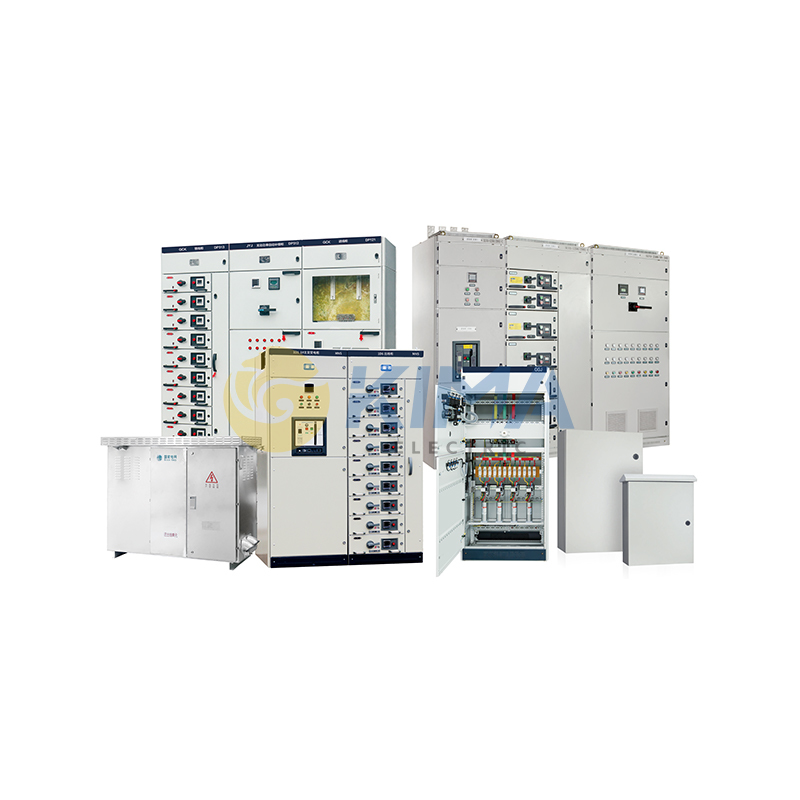
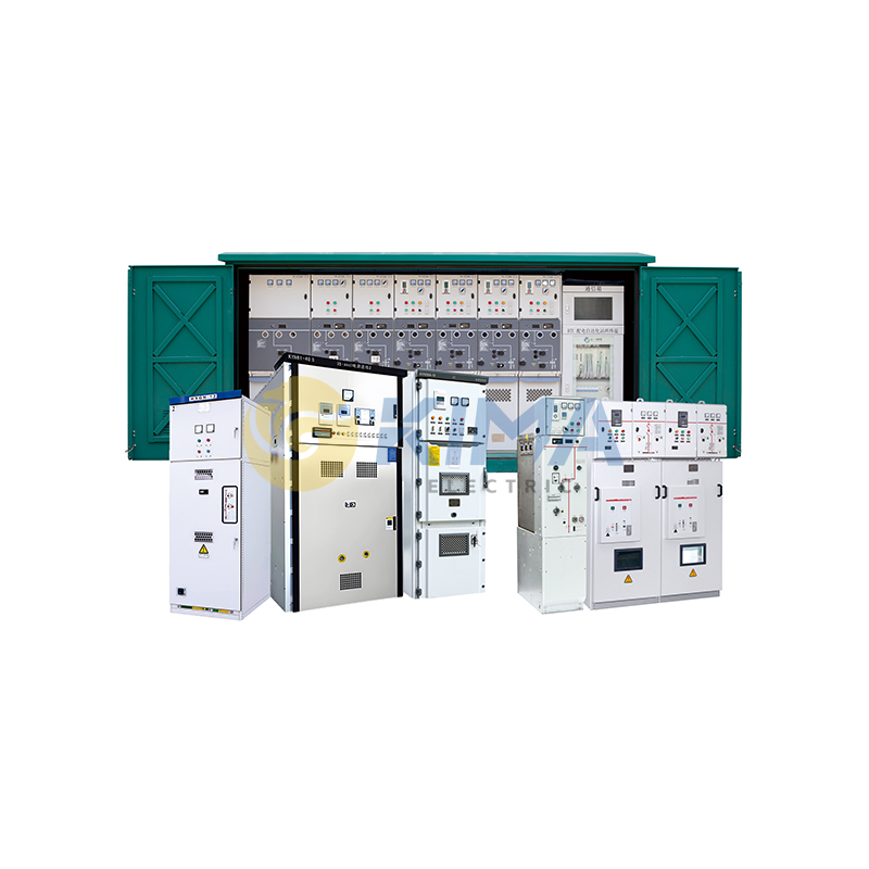
High Integration: Integrates transformation, distribution, protection, metering, monitoring, and reactive power compensation within a standard cabin, enabling factory preassembly and rapid on-site installation, significantly shortening project timelines.
Safety & Reliability: Equipped with a comprehensive relay protection system featuring over-current, instantaneous trip, over-voltage, under-voltage, gas, temperature, and other multi-level protection functions, ensuring safe and stable operation of the booster station and the grid.
Intelligent Operation: Built-in advanced automation and monitoring system supports remote data acquisition, status monitoring, and fault diagnosis, enabling unmanned or minimally staffed operation and reducing O&M costs.
Flexible Configuration: Transformer capacity, HV/LV side schemes, protection configuration, and communication interfaces can be flexibly configured to meet grid-connection requirements for projects of different scales and voltage levels.
Technical Parameters
|
Parameter |
Unit |
HV Switchgear |
Step-up Transformer |
LV Distribution Panel |
|
Rated Voltage |
kV |
12 / 24 / 35 |
0.8 / 10.5 / 35 |
0.4 / 0.8 |
|
Rated Current |
A |
630 / 1250 |
Customized per capacity |
2500 / 4000 / 6300 |
|
Short-circuit Breaking Current |
kA |
25 / 31.5 |
— |
50 / 65 / 85 |
|
Protection Class |
— |
IP4X |
IP20 |
IP54 |
|
Cooling Method |
— |
— |
ONAN / ONAF |
— |
|
Communication Interface |
— |
RS485 / Ethernet |
PT100 |
RS485 / Ethernet / 4G |
Information Required for Inquiry or Order Placement
Please provide the following accurate information when requesting a quotation or placing an order, so that we may perform technical calculations and schedule production:
|
Category |
Details |
|
Project Overview |
Project name, installation location, operating environment (e.g., altitude, max/min temperature, relative humidity, presence of corrosive gases or severe vibration, etc.). |
|
Product Model & Specifications |
Specify the model of the PV booster station, HV side rated voltage (kV), LV side rated voltage (V), and transformer rated capacity (kVA). |
|
HV Side Configuration |
1. HV switchgear scheme (e.g., incoming cabinet, outgoing cabinet, PT cabinet, metering cabinet, etc.). 2. Rated current (A) and short-circuit breaking capacity (kA). 3. Relay protection configuration requirements. |
|
Step-up Transformer Configuration |
1. Transformer type (e.g., oil-immersed, dry-type). 2. Rated capacity (kVA). 3. Primary and secondary voltage levels (kV). 4. Winding material: copper or aluminum. 5. Rated frequency (50Hz or 60Hz). 6. Connection group (e.g., Dyn11, YNd11). 7. Impedance voltage (%) and cooling method. |
|
LV Side Configuration |
1. LV incoming circuit breaker rated current (A) and breaking capacity (kA). 2. Whether SVG/SVC reactive power compensation is required, and capacity requirements. 3. Number and specifications of LV outgoing circuits. |
|
Automation & Monitoring System |
1. Specify electrical parameters and non-electrical signals to be monitored (e.g., temperature, humidity, access control, smoke, etc.). 2. Communication interface (e.g., RS485, Ethernet) and protocol requirements (e.g., Modbus RTU/TCP, IEC 61850, etc.). |
|
Appearance & Dimensions |
Specify cabin size limitations (if special transport or site constraints apply), enclosure material (e.g., color steel composite panel, stainless steel), color (provide color card number or RAL code), and anti-corrosion grade. |
Key Technical Parameters & Configuration Requirements
|
Category |
Details |
|
Reactive Power Compensation (SVG/SVC) |
Specify whether SVG/SVC is required, including compensation capacity, response time, and other technical requirements. |
|
Grounding Method |
Specify grounding method requirements for HV and LV systems (e.g., neutral point ungrounded, grounded via arc suppression coil, grounded via small resistance, etc.). |
|
Auxiliary Systems |
Specify requirements for cabin lighting, maintenance sockets, industrial A/C or ventilation systems, fire protection systems (e.g., automatic fire suppression devices), etc. |
|
Special Function Requirements |
If video surveillance, access control systems, anti-condensation devices, etc. are required, please provide a written description in advance. |
Ordering Process & Precautions
|
Step |
Description |
|
Technical Agreement |
For non-standard products or complex projects, both parties must sign a detailed Technical Agreement prior to production scheduling, which shall serve as an annex to the contract with equal legal force. |
|
Drawing Confirmation |
We will provide general assembly drawings, foundation drawings, and single-line diagrams. Please sign and confirm promptly. Any schedule delay resulting from late confirmation shall be borne by the client. |
|
Change Management |
After order confirmation and drawing sign-off, any technical or commercial changes must be submitted in writing and re-confirmed by both parties before implementation. Cost increases or schedule delays caused by changes shall be borne by the requesting party. |
|
Site Coordination |
Ensure on-site foundation construction strictly follows our provided foundation drawings, with adequate space reserved for hoisting and transportation access. If on-site installation guidance or commissioning services are required, please schedule in advance. |
If you are looking for reliable power support for your project, please contact the Kima Electric team. We are ready to provide you with the best solutions.
Convenient Inquiry Process
You may contact us through various channels, including our website and email. You can also download and fill out the "Inquiry Application Form" from our official website, or directly provide your existing technical documents and drawings as the basis for requirements assessment. We will provide you with a quotation as soon as possible.
Production & Quality Control
|
Aspect |
Details |
|
Technical Review |
Prior to formal production, we will provide detailed technical proposals including specification parameters and structural drawings for your review and confirmation. |
|
Quality Management |
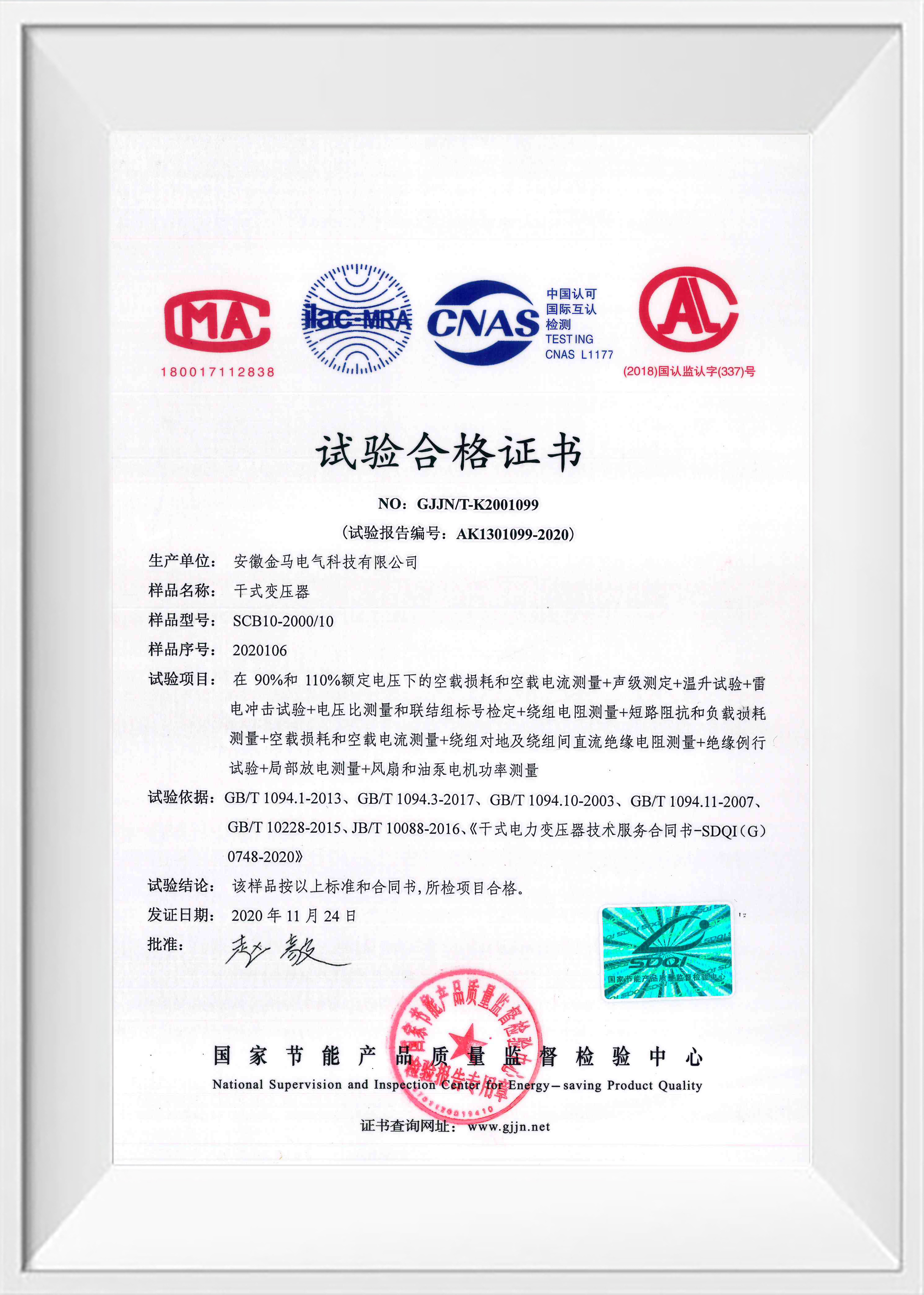
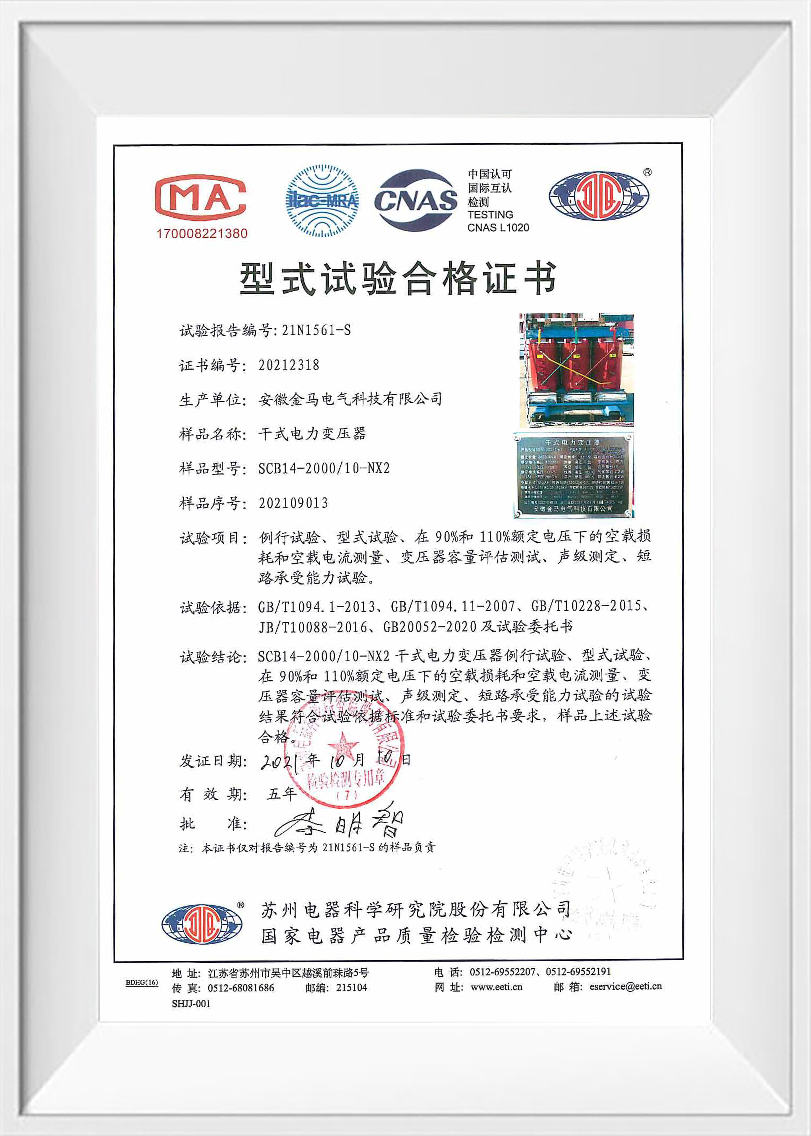
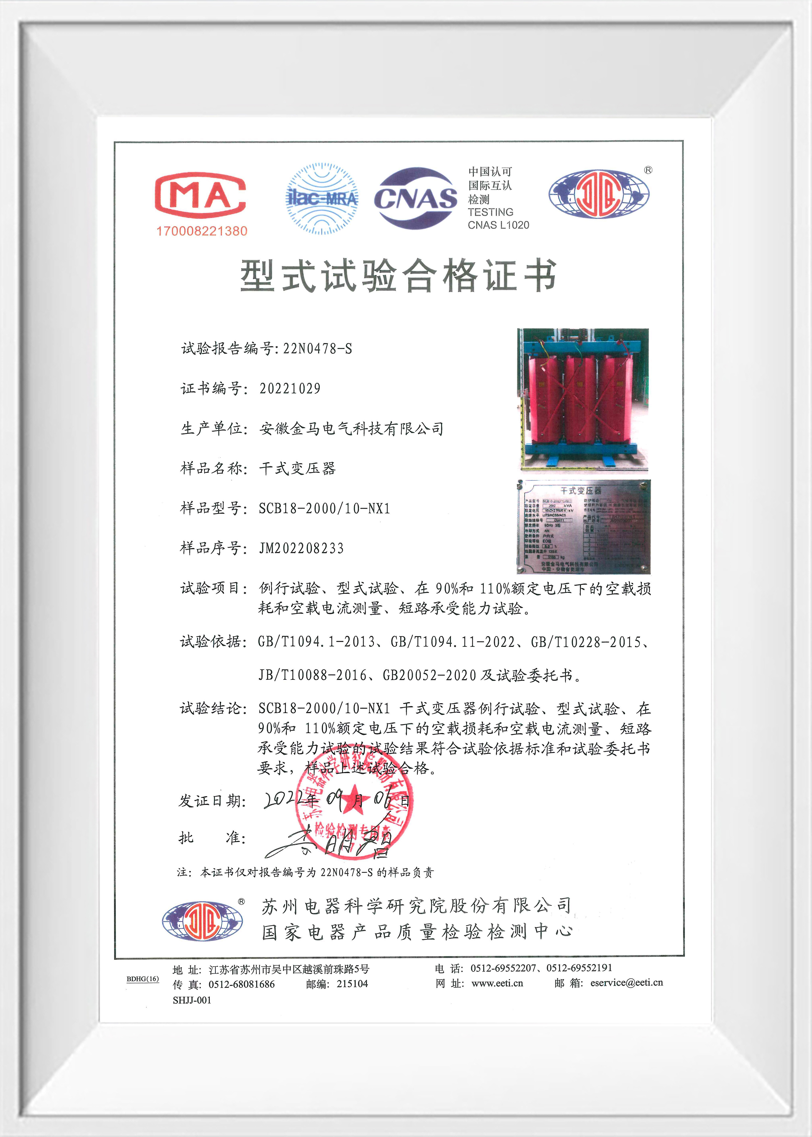
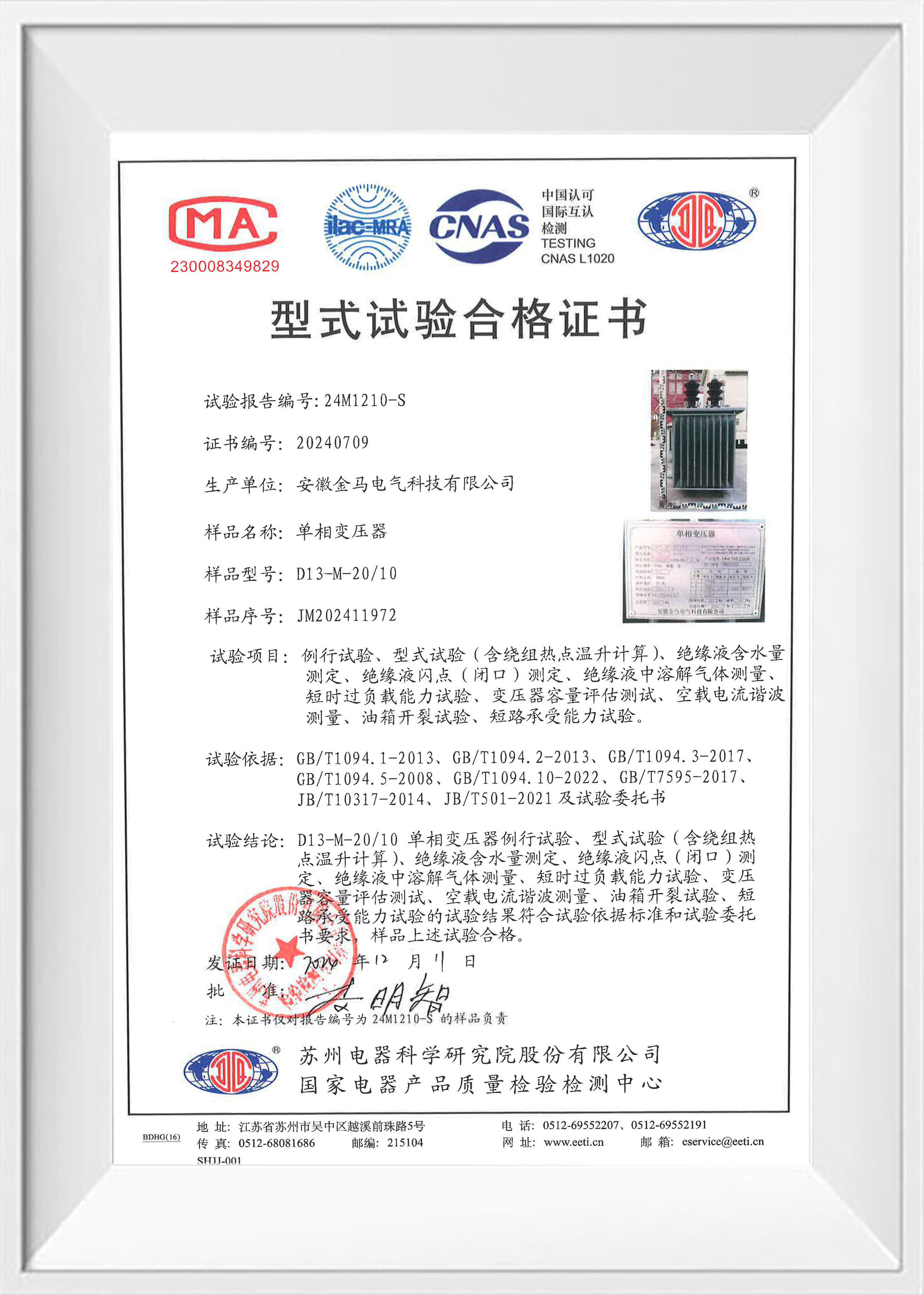
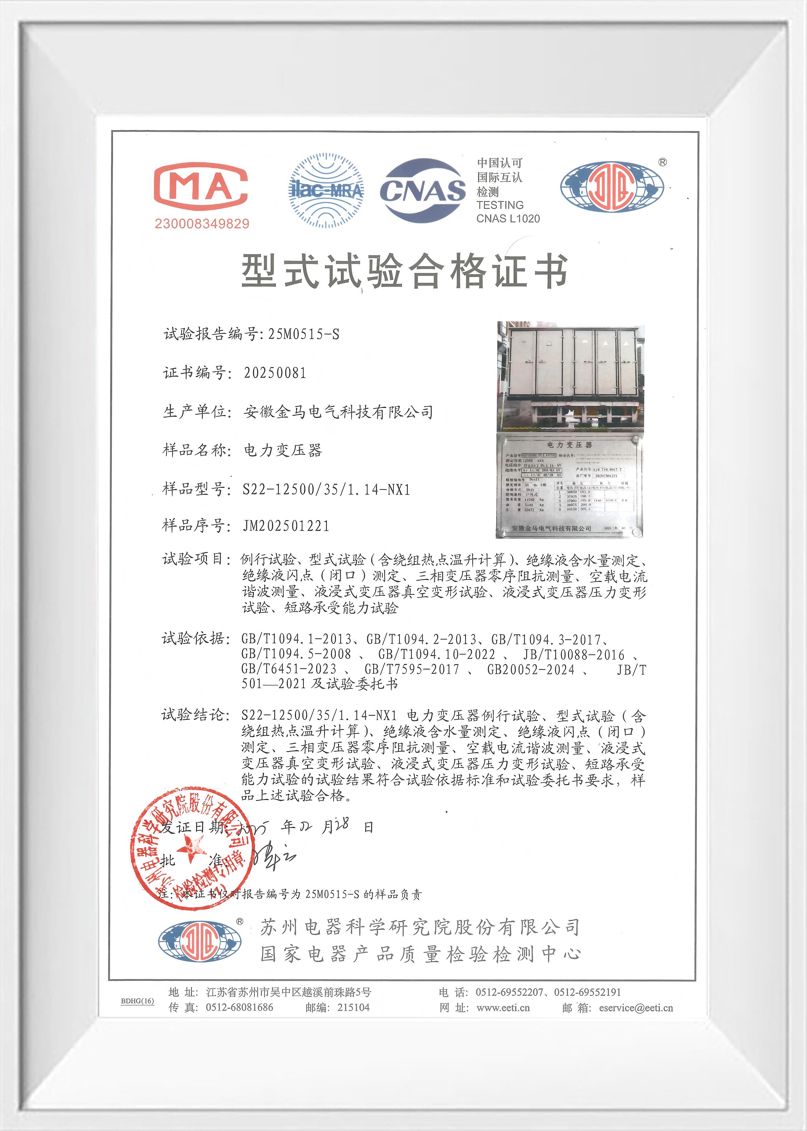
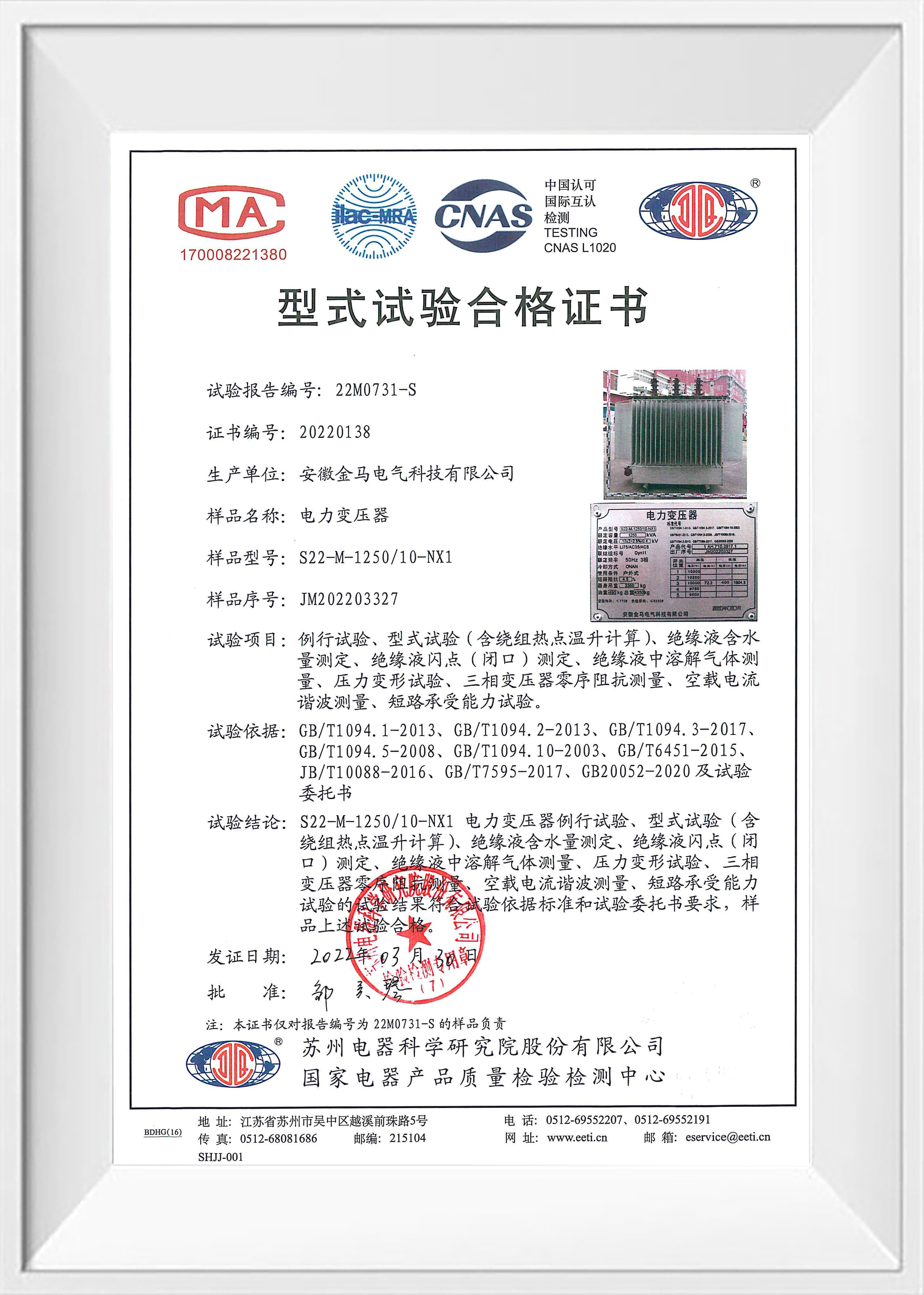
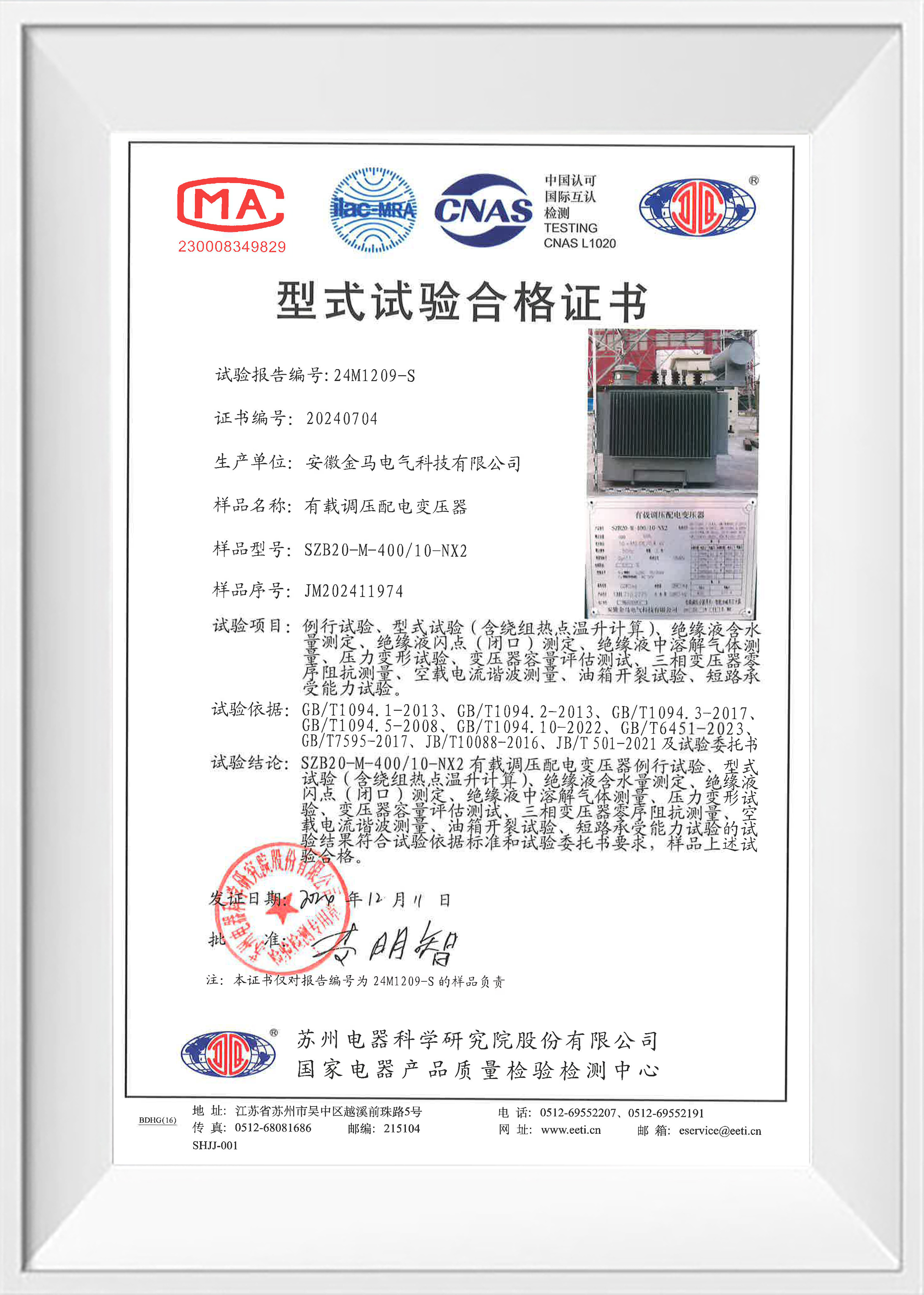
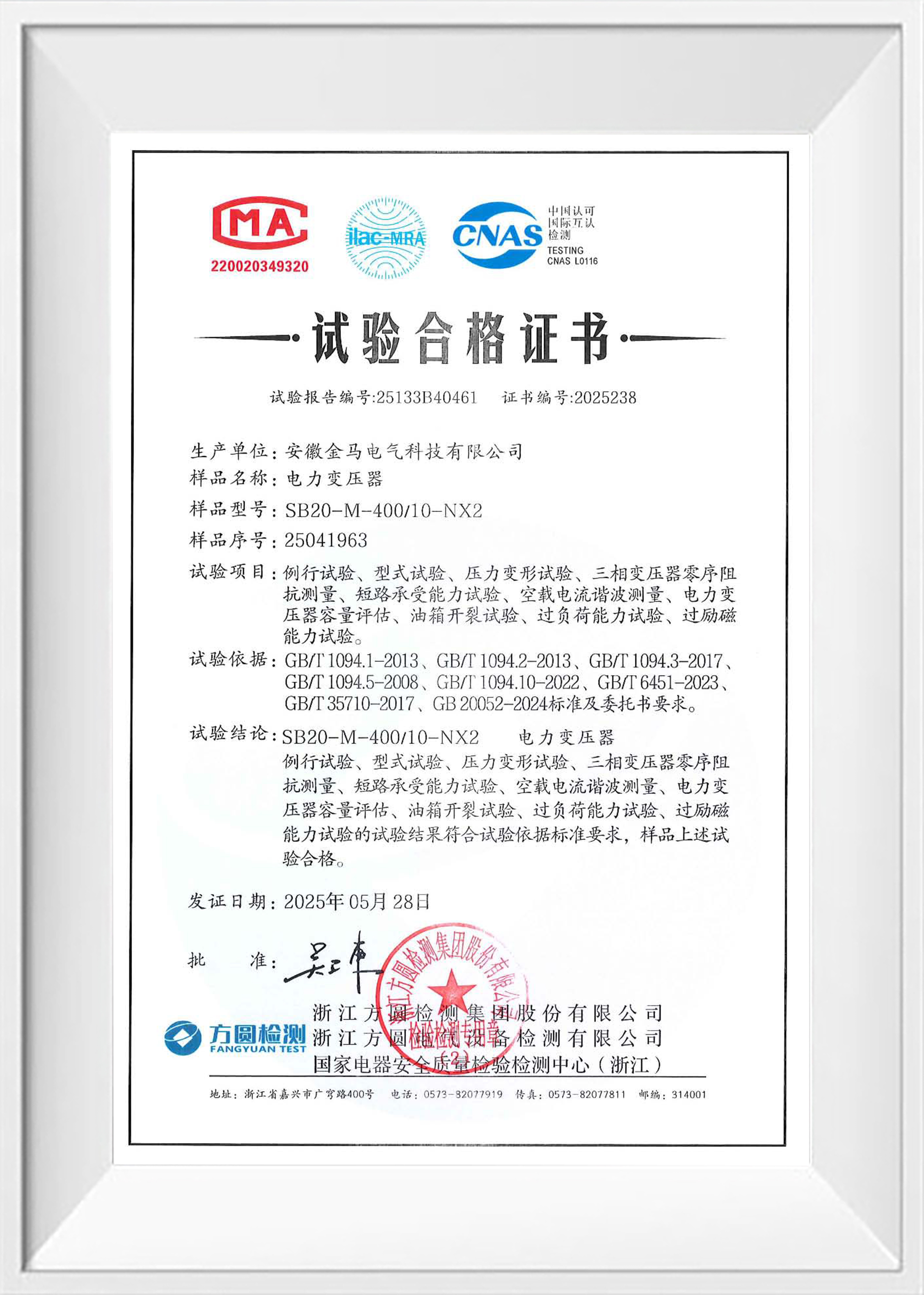
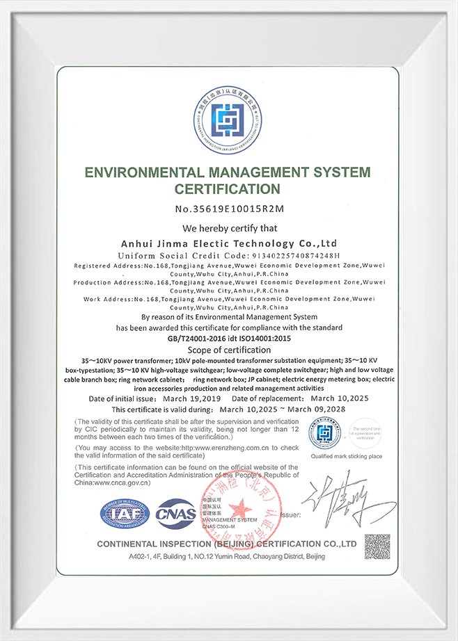
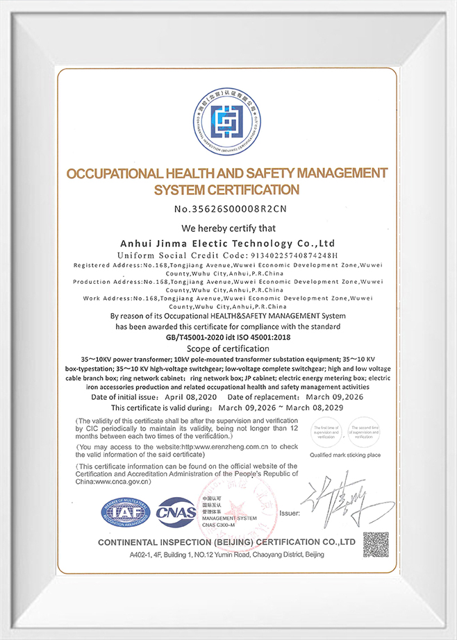
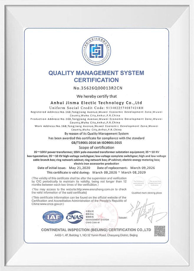
We strictly implement the ISO quality management system, with comprehensive monitoring of raw materials, production processes, and finished product inspection to ensure stable and reliable quality for every customized product. |
Delivery & After-Sales Service
|
Aspect |
Details |
|
Packaging & Shipping |
Specialized packaging and transportation solutions compliant with international standards, ensuring absolute safety during long-distance transport. |
|
Documentation |
Each shipment includes detailed user manuals, maintenance manuals, and related technical documentation. |
|
Installation & Commissioning |
Remote or on-site installation guidance and commissioning services are available upon request. |
|
After-sales Support |
Comprehensive technical consultation, troubleshooting, and spare parts supply to ensure long-term stable operation of the equipment. |
Who Are We
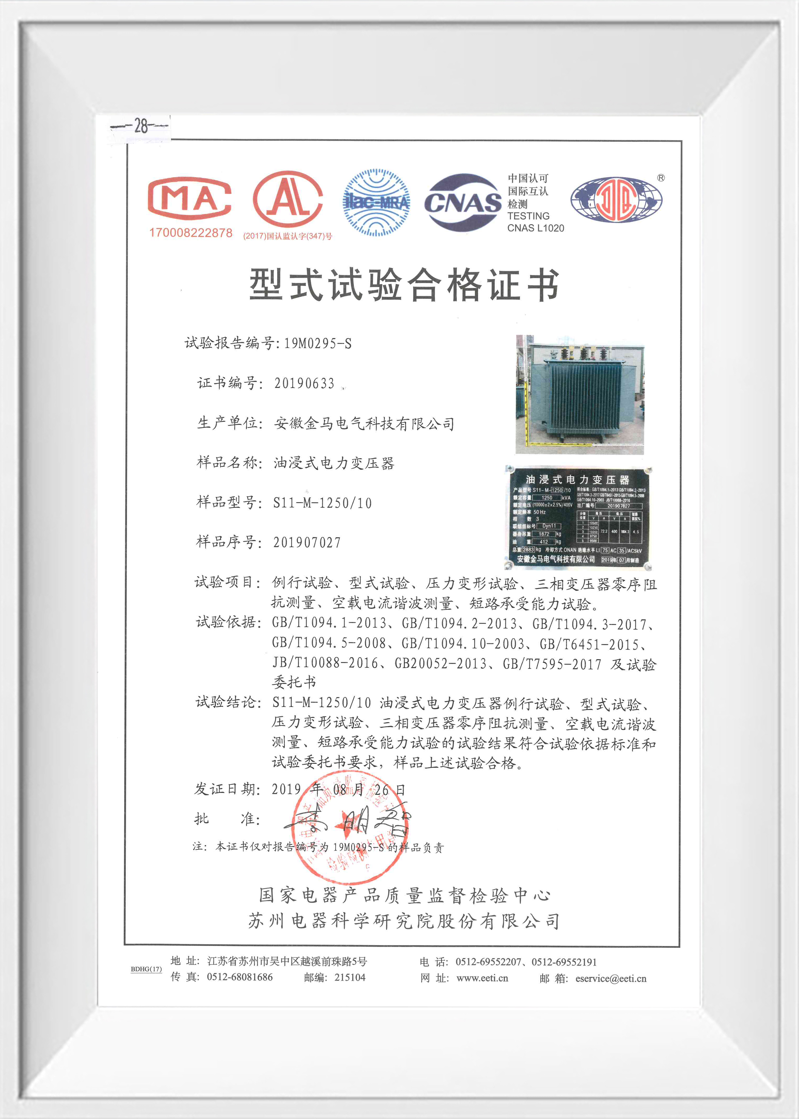
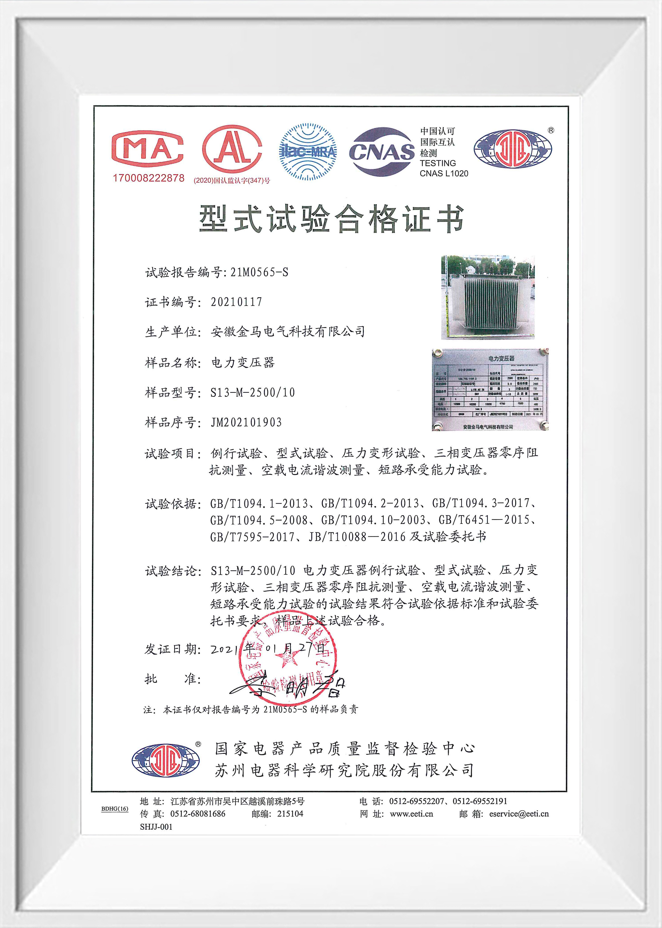
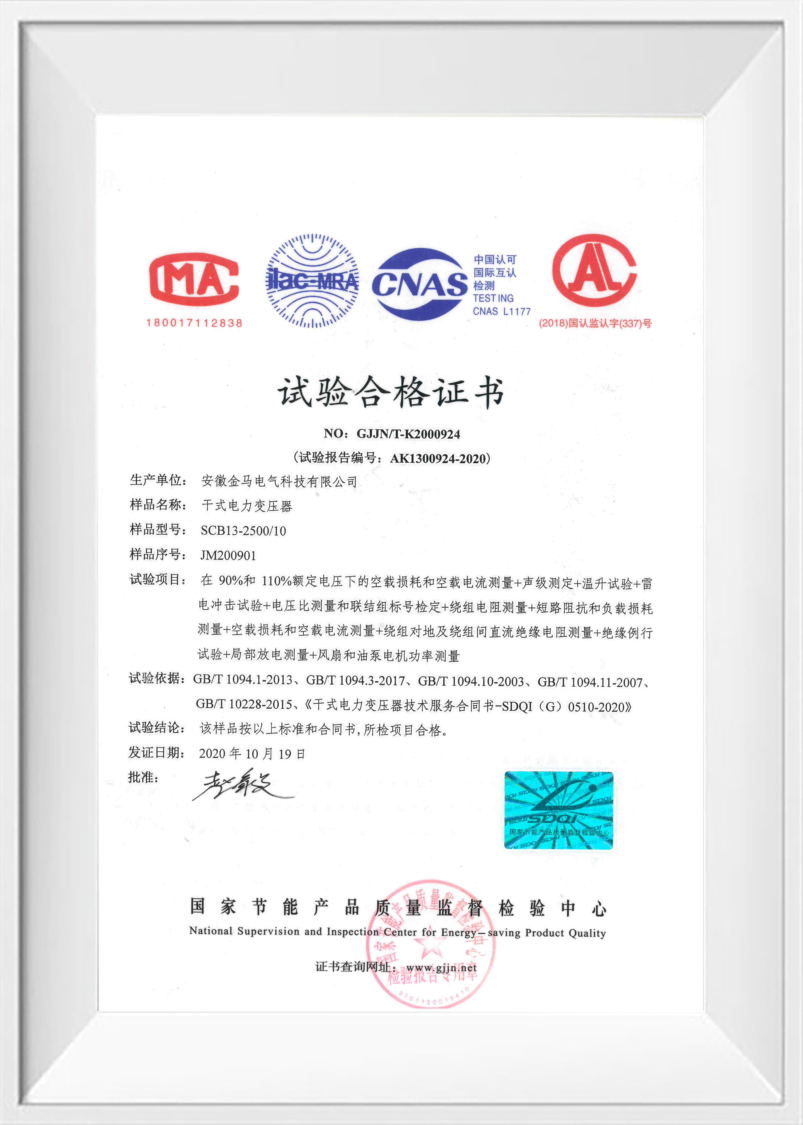
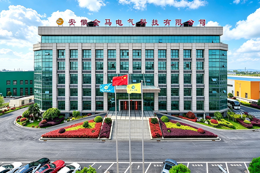
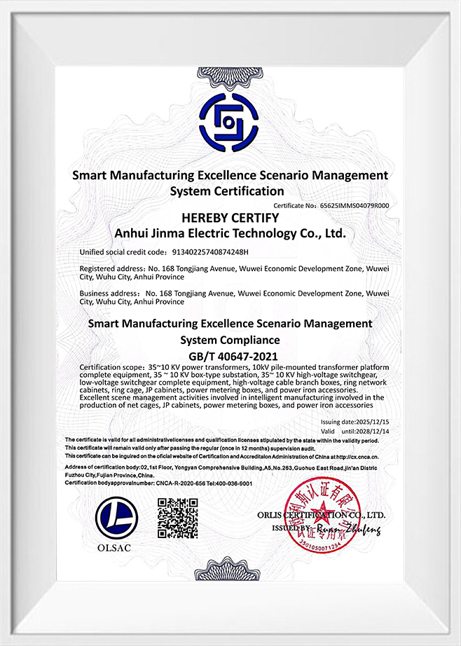
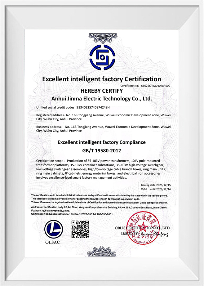
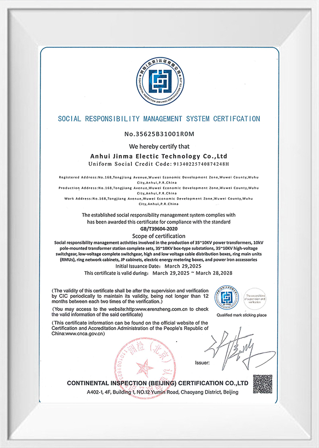
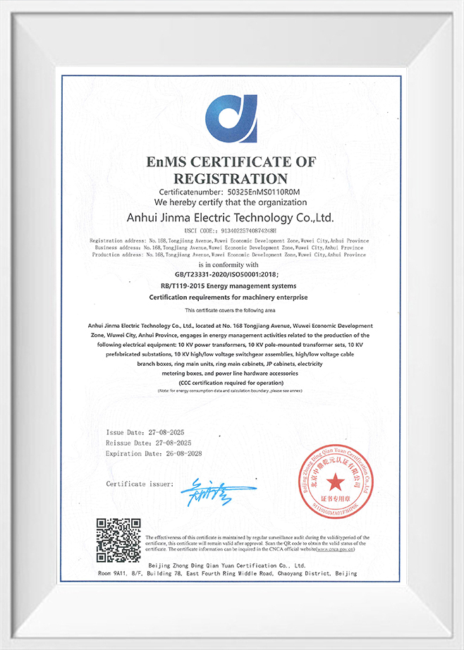
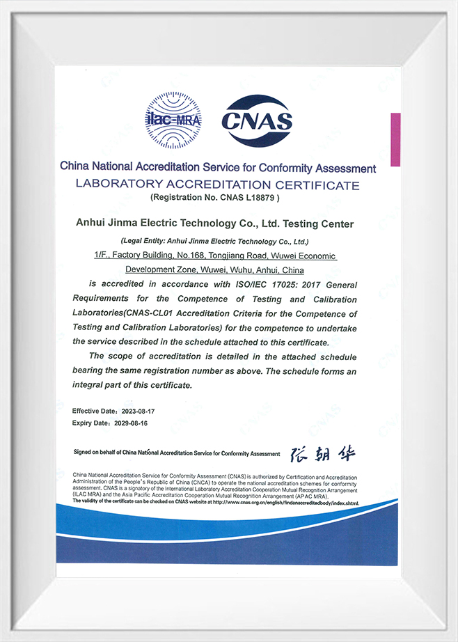
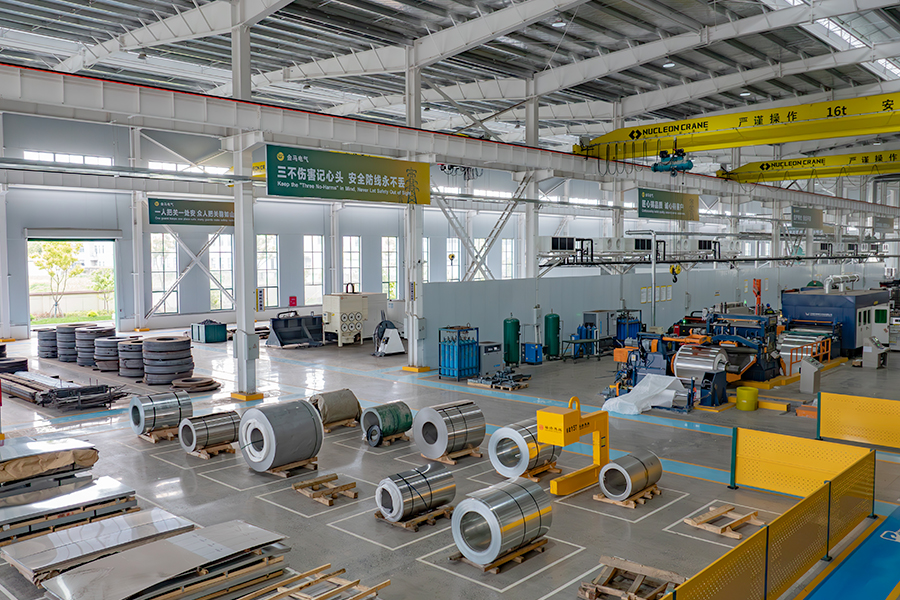
Kima Electric is a global brand under Anhui Jinma Electric Technology Co., Ltd.. and is a professional manufacturer of transformers &power transmission and distribution equipment in China. Established in 2001 and located in Wuwei, Wuhu City, Anhui Province, China ,the company occupies a facility spanning 93 mu (approximately 62,000 square meters) with a building area of 51,000 square meters and a professional team of over 180 personnel. With over 20 years of industry expertise, we have developed a comprehensive production system, rigorous quality control, and a culture of continuous innovation. We are committed to providing global customers with exceptional quality assurance and professional services.
-
0 +
Factory Area (㎡)
-
0 +
Employees
-
0 +
Industry Experience
-
0 +
Countries Sale

> KIMA, Your Trusted Global Partner
for Electrical Power Equipment <
Anhui Kima Electric Technology Co., Ltd.
-
 +86 400 0553 633
-
+86 199 4451 2191
-
 info@kimaelectric.com
-
 No. 168 Tongjiang Avenue, Wuwei Economic Development Zone, Wuwei City, Anhui Province, ChinaNote: Kima is a brand of Anhui Jinma Electric Technology Co., Ltd., China.
+86 199 4451 2191

PRODUCTS
RESOURCES
COMPANY LOCATION MAP
Copyright © Anhui Kima Electric Technology Co., Ltd. All Rights Reserved

-
 0
0
-
-
info@kimaelectric.com
-